Train control system

a technology of control system and train, applied in the direction of vehicle position/course/altitude control, process and machine control, instruments, etc., can solve the problems of increasing cost and ensuring installation positions, and achieve the effect of misselection

Inactive Publication Date: 2017-05-30
NIPPON SIGNAL CO LTD
View PDF30 Cites 2 Cited by
  • Summary
  • Abstract
  • Description
  • Claims
  • Application Information

AI Technical Summary

Benefits of technology

[0018]According to the embodiment of the invention according to claim 1, the on-board device is provided with the plurality of processing units simultaneously performing processes in different drive modes, and the drive mode determining unit that selects either one of process results of processing units to be used in a travel control. Thus, only by installing a single on-board device, the system can correspond to the plurality of drive modes. It is unnecessary to mount a plurality of on-board devices like in a conventional technique. Therefore, the cost can be reduced and it is unnecessary to assure places to install a plurality of on-board devices.
[0021]According to the embodiment of the invention according to claim 4, the train control system further includes a change-over switch of a drive mode, that is installed in the driver's cab of the train and switches selection of any of the processing units by the drive mode determining unit, and the change-over switch has a lock mechanism for locking the change-over switch unless a predetermined condition is satisfied. Therefore, the drive mode can be reliably prevented from being switched by mistake during travel of a train, uncontrollability of a train can be reliably prevented, and safe operation of a train can be assured.

Problems solved by technology

However, since a plurality of on-board devices has to be mounted, there are problems such that the cost increases and installation positions have to be assured.

Method used


Image

  • Train control system
  • Train control system
  • Train control system

Examples


Embodiment Construction

[0029]Hereinbelow, an embodiment of the present invention will be described with reference to the accompanying drawings.

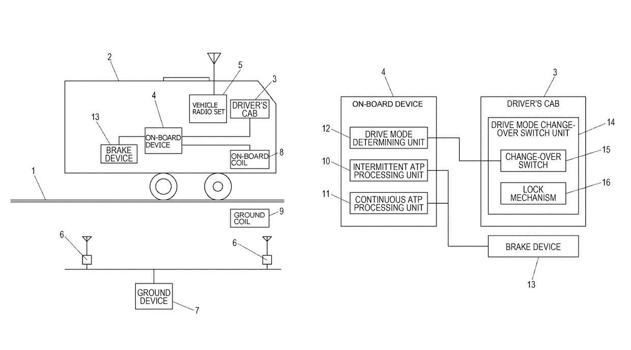
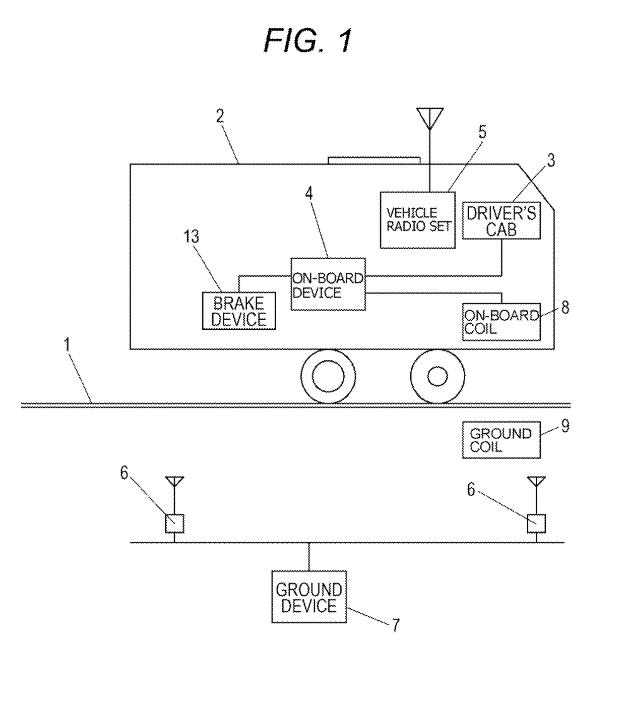
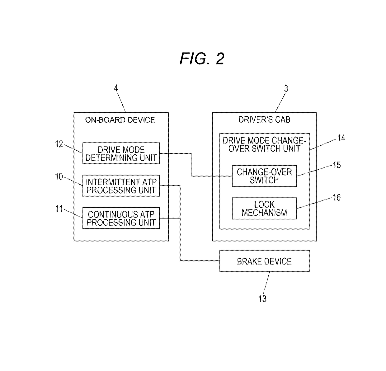
[0030]FIGS. 1 and 2 are schematic configuration views illustrating an embodiment of a train location detecting system according to the present invention. In the embodiment, a driver's cab 3 in which the driver performs various operations is installed in a train 2 traveling on a predetermined track 1, and an on-board device 4 that controls the train 2 on the basis of an operation of the driver's cab 3 is mounted. The on-board device 4 is configured to perform various controls such as a speed control and a braking control on the train 2. In the train 2, a vehicle radio set 5 connected to the on-board device 4 is also mounted.

[0031]A plurality of wayside radio sets 6 that transmits information to and receives information from the vehicle radio set 5 are installed at predetermined intervals along the track 1 of the train 2, and a ground device 7 is connected to the way...


PUM


Abstract

A train control system of the present invention capable of controlling a train in a plurality of drive modes by a single on-board device, includes an on-board device 4 mounted on a train 2 traveling on a predetermined track 1; a continuous ATP processing unit 11 and an intermittent ATP processing unit 10 that is provided in the on-board device 4 and simultaneously performs processes in a continuous ATP drive mode by a continuous ATP system and an intermittent ATP drive mode by an intermittent ATP system; and a drive mode determining unit 12 that selects either one of process results to be used in a travel control, of the continuous ATP processing unit 11 and the intermittent ATP processing unit 10.

Description

[0001]This application is a continuation application of PCT / JP2012 / 074287, filed on Sep. 21, 2012.BACKGROUND OF THE INVENTION[0002]1. Field of the Invention[0003]The present invention relates to a train control system, and more specifically, relates to a train control system capable of controlling a train in a plurality of drive modes by a single on-board device.[0004]2. Description of Related Art[0005]Conventionally, in a train control system using a so-called radio distance measurement system, a vehicle radio set is mounted on a train, a wireless network is formed between the vehicle radio set and a plurality of wayside radio sets which is spatially separated and disposed along a wayside of a track on which the train travels, and then, wireless propagation delay (time) between an on-board antennal of the vehicle radio set and a railroad antenna of the wayside radio set is measured, to detect a train location, so that train control is performed on the basis of the detected train lo...

Claims


Application Information

Patent Timeline
Patent Type & Authority Patents(United States)
IPC IPC(8): G05D1/00G05D3/00B61L3/12B61L15/00B61L25/02G06F17/00G06F7/00
CPCB61L25/02B61L3/125B61L15/0063B61L25/026Y02T10/7258Y02T10/72
Inventor MYOKEI, KENICHI
Owner NIPPON SIGNAL CO LTD
Why Eureka
Try Eureka