Eureka AIR delivers breakthrough ideas for toughest innovation challenges, trusted by R&D personnel around the world.

Osteotome

a technology of osteotomy and bone, which is applied in the field of osteotomy, can solve the problems of compromising the directional accuracy of the technique, unable to achieve without mechanical means, and the cellous bone is not easily susceptible to cutting, so as to achieve rapid and convenient removal and accurate results.

Active Publication Date: 2017-09-19
ORTHOFIX SRL
View PDF37 Cites 3 Cited by
  • Summary
  • Abstract
  • Description
  • Claims
  • Application Information

AI Technical Summary

Benefits of technology

[0010]It is hence an object of the present disclosure to provide a tool for cutting bone, particularly bone adjacent an arthroplasty implant, that obviates the above disadvantages and allows accurate, rapid and convenient removal of such implants as part of a revision procedure.

Problems solved by technology

While not as strong as the structural bone of the wall of the femur, the pelvis or other bone, cancellous bone is not easily susceptible to cutting using the tools devised for revising cement-anchored implants, and it has become necessary to attack cancellous bone mechanically in order to revise such implants.
Furthermore, in order to remove a prosthesis, it may be necessary to remove portions of cortical bone, which cannot be achieved without using mechanical means.
The force required can be so great as to compromise the directional accuracy of the technique, and may thereby damage surrounding structural bone, especially if it is weakened by osteoporosis or the like.
These may also be difficult to guide accurately, and flexure in their elongate rotating drive shafts may lead to unacceptable collateral damage in surrounding structural bone.
This approach also produces inconveniently large quantities of bone swarf, which must be removed to allow clear visualisation of the point at which the burr is cutting.
Furthermore, high-speed burrs lead to significant localised frictional heating, which may also harm adjacent bone, tissue or marrow.
Manual sawing through bone is a slow, tiring process, also leading to localised heating and copious bone swarf.
In any case, conventional bone saws could not easily be inserted or operated between a hip or other joint prosthesis shaft and an inner wall of a femur, or between a part-spherical acetabular shell and a pelvic bone, for example.

Method used


Image

  • Osteotome
  • Osteotome
  • Osteotome

Examples


Embodiment Construction

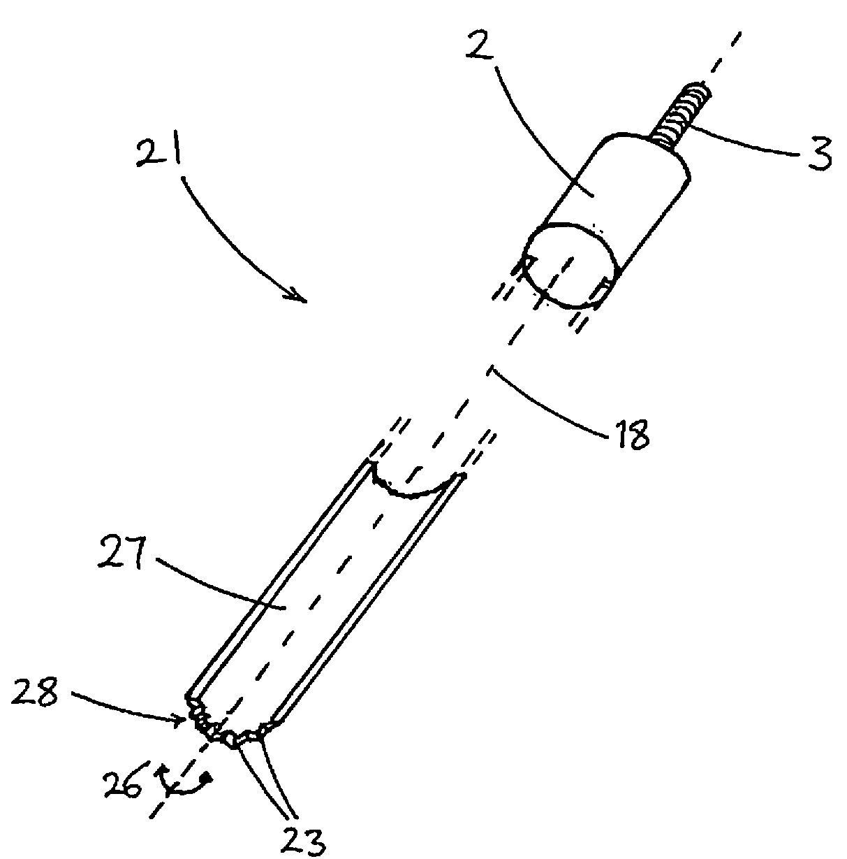
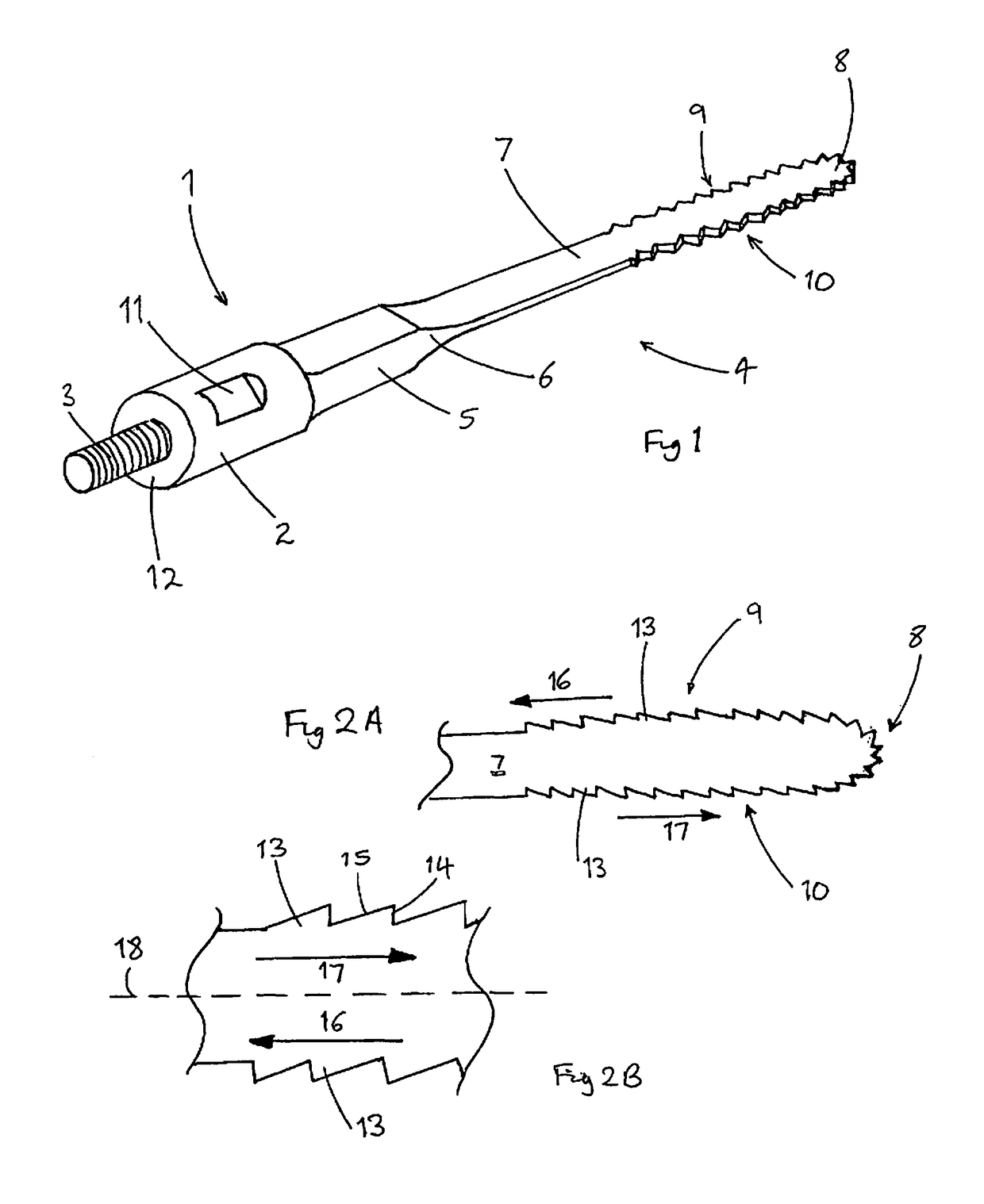
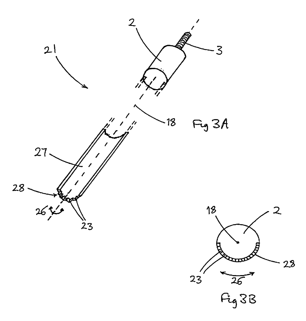
[0056]Referring now to the Figures and to FIG. 1 in particular, a first osteotomy tool 1 comprises a cylindrical connecting body 2 provided at a proximal end with a threaded spigot 3, by which the tool 1 may detachably be connected to a generator of ultrasonic vibrations (not shown). An elongate blade portion 4 of the tool 1 extends from a distal end of the connecting body 2, and is aligned generally coaxially therewith.

[0057]The blade portion 4 comprises a proximal blade root 5 having a substantially rectangular cross-section and linked by a tapered portion 6 to a thin, flat elongate blade 7 with a generally rounded distal tip 8. A distal portion of the blade 7 has two oppositely-facing lateral cutting edges 9, 10. Each of the lateral cutting edges 9, 10 and the tip 8 is provided with a plurality of teeth 13, as shown in more detail in FIGS. 2A and 2B. A proximal portion of the blade 7 is toothless, although the relative lengths of the toothed and toothless portions may vary from t...


PUM


Abstract

A tool (1, 31) for cutting bone comprises an elongate blade (7, 37) connectable to a generator of longitudinal-mode ultrasonic vibrations. The blade (7, 37) has two lateral cutting edges (9, 10) linked by a rounded distal tip (8). A series of triangular teeth (13) extends along each cutting edge (9, 10) and the distal tip (8). The blade (37) may taper towards each cutting edge (9,10) and the distal tip (8). A variant of the tool (21) comprises an elongate part-cylindrical blade (27) connectable to a generator of torsional-mode ultrasonic vibrations. The blade (27) has a cutting edge at its distal tip (28) provided with a plurality of triangular teeth (23). All forms of the tool (1, 21, 31) are particularly suitable for cutting cancellous bone around an implant to be removed during revision of a joint arthroplasty.

Description

BACKGROUND[0001]1. Technical Field[0002]The present disclosure relates to a tool for cutting into or through bone, for example during orthopaedic surgery. More particularly, but not exclusively, it relates to a tool for cutting through cortical or cancellous bone, for example to separate a joint prosthesis from surrounding bone as part of a revision procedure.[0003]2. Prior Art[0004]A frequently required procedure in orthopaedic surgery is revision of a joint arthroplasty, for example revision of a hip joint replacement, should an implanted prosthesis break or wear unacceptably over its articulating surface. The present disclosure will be described in relation to its use in hip joint revision, but is equally applicable to other joints and the terms “hip”, “pelvis” and “femur” may be replaced as necessary. In many cases, an implanted prosthesis is secured in a cavity within a bone, such as a femur, using polymeric organic cement such as polymethylmethacylate. Tools have been devised ...

Claims


Application Information

Patent Timeline
Patent Type & Authority Patents(United States)
IPC IPC(8): A61B17/32A61B17/16A61B17/14
CPCA61B17/16A61B17/142A61B17/144A61B17/1628A61B17/1637A61B17/320068A61B17/1642A61B17/1664A61B2017/320072A61B2017/320077
Inventor YOUNG, MICHAEL JOHN RADLEY
Owner ORTHOFIX SRL
Why Eureka
Eureka Blog
Learn More