
Medical device for evaluating a temperature signal

a technology of temperature signal and medical device, which is applied in the field of medical device that evaluates temperature signal, can solve the problems of affecting the accuracy of the exact amount of energy transferred from the electrode to the tissue, affecting the accuracy of the measurement, and unable to come to a conclusion regarding the presence of reliable wall conta

Active Publication Date: 2017-09-26
BIOTRONIK AG
View PDF9 Cites 0 Cited by
  • Summary
  • Abstract
  • Description
  • Claims
  • Application Information

AI Technical Summary

Benefits of technology

[0014]The inventors have recognized that periodic fluctuations of a signal level of a temperature signal, in one or more embodiments, provide a quick criterion to determine constant wall touching. As such, in at least one embodiment, it possible to save energy, since an unnecessary energy transfer, should the electrode line not be in contact with the wall, to a fluid surrounding a wall may be reduced. In at least one embodiment, the criterion may be used to decide more quickly when the energy transfer is to be interrupted. In one or more embodiments, the electrode line may then be realigned in order to produce wall contact. In at least one embodiment, the criterion may also be used for example to interrupt the energy transfer in the case of poor wall contact in a renal denervation procedure. In one or more embodiments, good wall contact may be identified faster, for example between a bipolar electrode line or a bipolar catheter and the wall, if there is no frequency component of the heart rate in the spectrum of temperature. The energy transfer, in at least one embodiment, may be interrupted more quickly should the spectrum have a frequency component of the heart rate. According to one or more embodiments, the quicker interruption of the energy transfer in the event of poor wall contact reduces blood clotting and the formation, triggered thereby, of blood clots, which may lead to blockages in the blood vessels and damage in the body of the patient.
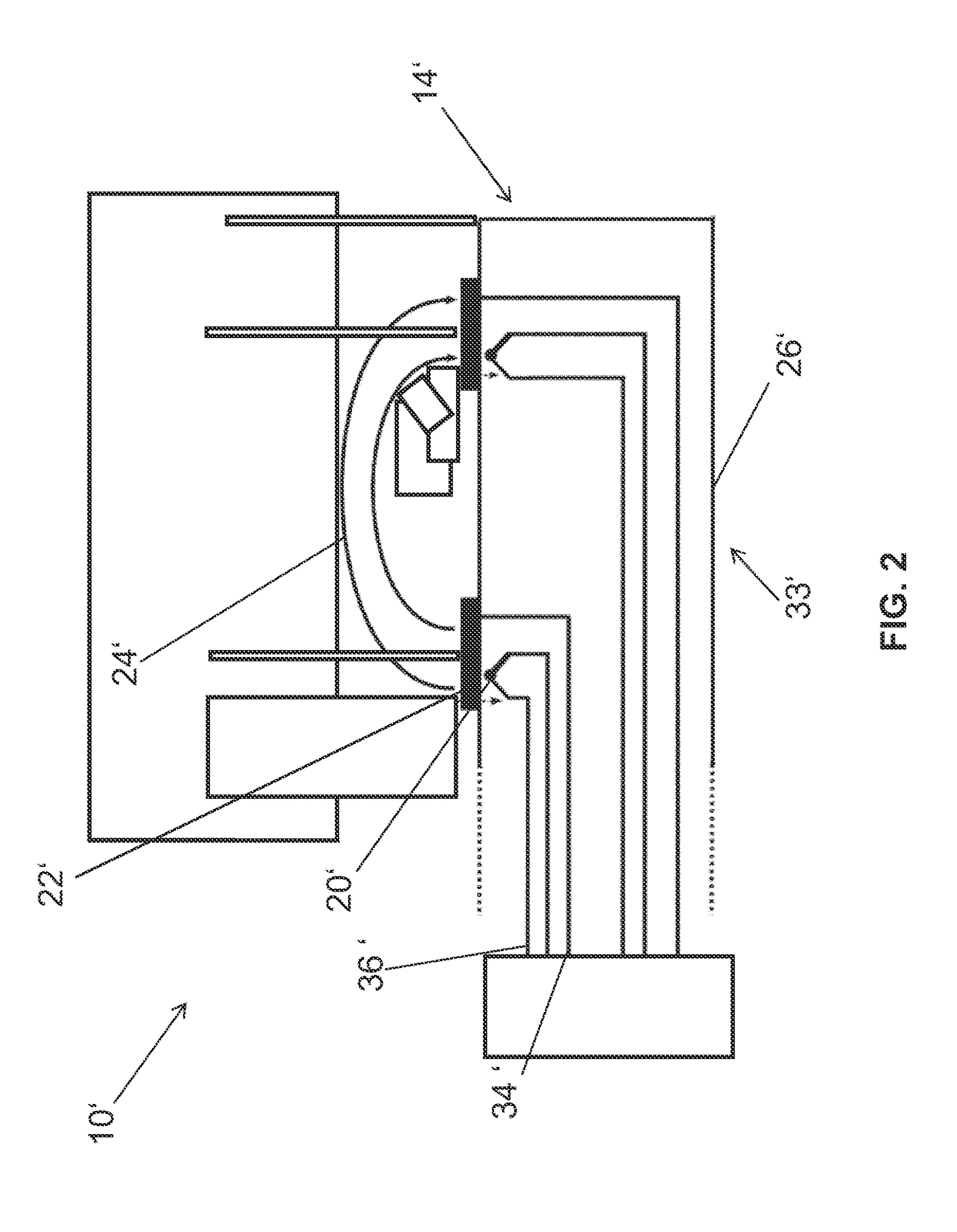
[0023]One or more embodiments of the invention use the measuring principle for the identification of constant wall touching in the case of renal denervation even before therapy is begun in order to determine the quality of the wall contact. For example, in at least one embodiment, with a bipolar catheter, a low power that may lead only to an insignificant heating of the environment surrounding the catheter may be delivered for a short period of time. As such, in at least one embodiment, the quality of the wall contact may be concluded on the basis of an evaluation of the temperature data.
[0031]T=N·1fs.With a sampling rate of 22 Hz, in one or more embodiments, a recording over 6 s may be necessary for a pulse rate resolution of 0.67 Hz (10 bpm). According to at least one embodiment, the method allows for quick detection of the pulse rate in the data, whereby it is ensured that the energy transfer is switched off reliably. One or more embodiments of the invention may determine within 3 s after onset of the energy transfer whether a component of the pulse rate is present in the data.

Problems solved by technology

The process of checking the exact amount of energy that is transferred from the electrodes to the tissue is generally impeded by the fact that the position of the catheter at the site of use cannot be accurately checked.
In this case, the clumped blood may cause damage to the organs due to the closure of blood vessels, and in the worst case scenario may also close brain or heart vessels, which may lead to the death of the patient.
Animal tests have shown however that, by evaluating the impedance alone, it may not be possible to come to a conclusion regarding the presence of reliable wall contact.
The evaluation of the temperature rise is generally time-consuming however, which is a disadvantage with use as a switch-off criterion.

Method used


Image

  • Medical device for evaluating a temperature signal
  • Medical device for evaluating a temperature signal
  • Medical device for evaluating a temperature signal

Examples


Embodiment Construction

[0048]The following description is of the best mode presently contemplated for carrying out at least one embodiment of the invention. This description is not to be taken in a limiting sense, but is made merely for the purpose of describing the general principles of the invention. The scope of the invention should be determined with reference to the claims.

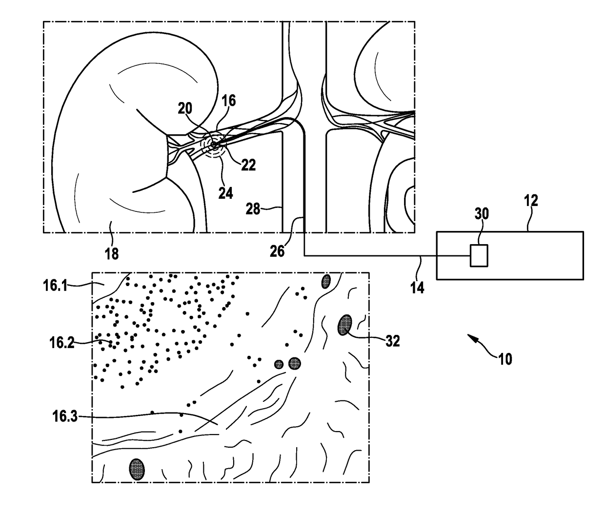
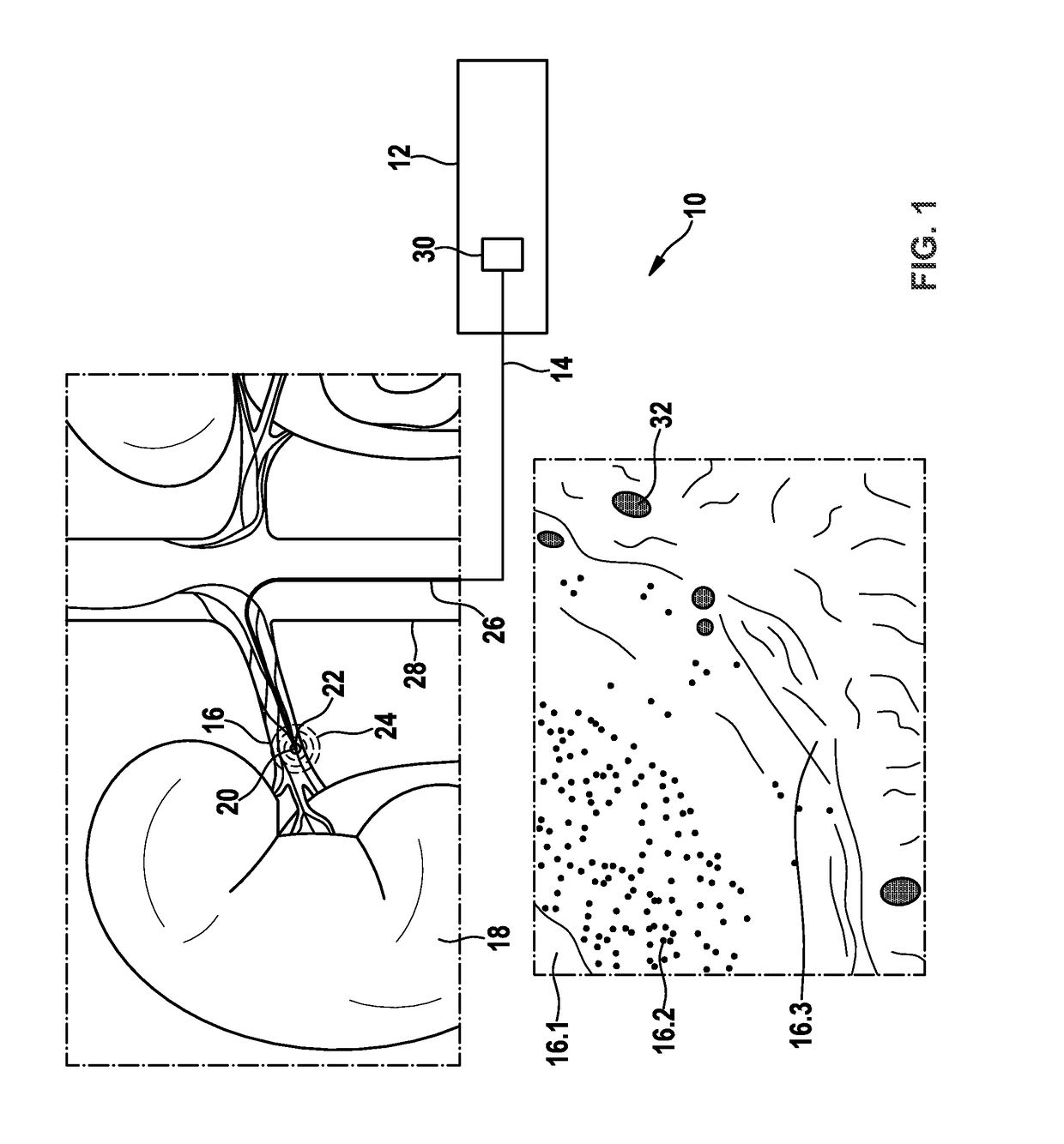
[0049]FIG. 1 shows a first exemplary embodiment of a medical device 10 having an evaluation unit 12 and an electrode line 14, which is introduced into a renal artery 16 of a kidney 18 according to one or more embodiments of the invention. The lower part of FIG. 1 shows a part of a cross section of a renal artery vessel 16 with the vessel volume 16.1, media 16.2 and adventitia 16.3. One or more embodiments of the invention may include a temperature sensor 20 that delivers a temperature signal of the environment surrounding an ablation electrode 22, which may change due to an energy transfer 24 of the ablation electrode 22. At least ...


PUM


Abstract

A medical device including an evaluation unit and an electrode line. The electrode line includes at least one temperature sensor. The temperature sensor delivers a temperature signal to the evaluation unit. The evaluation unit evaluates periodic fluctuations of a signal level of the temperature signal and generates an evaluation output signal qualifying constant wall touching of the electrode line according to whether periodic fluctuations of a signal level of the temperature signal lie below or above a predetermined limit value.

Description

[0001]This application claims the benefit of U.S. Provisional Patent Application 61 / 882,649 filed on 26 Sep. 2013, the specification of which is hereby incorporated herein by reference.BACKGROUND OF THE INVENTION[0002]Field of the Invention[0003]Embodiments of the invention generally relate to a medical device that evaluates a temperature signal.[0004]Description of the Related Art[0005]Catheters are often used nowadays in medical applications in order to reach regions or cavities of a patient that are located within the body. Catheters are generally flexible tubes, which may carry out various functions depending on their design. For example, a catheter may be equipped with electrodes in order to transmit energy to tissue arranged around the electrodes. Catheters having electrodes are typically used for example for renal denervation, in which afferent sympathetic nerve fibers (of the sympathetic nervous system) in the renal arteries are selectively severed or cauterized by the trans...

Claims


Application Information

Patent Timeline
Patent Type & Authority Patents(United States)
IPC IPC(8): A61B18/14A61B18/12A61B18/00A61B90/00
CPCA61B18/1492A61B18/1206A61B18/1233A61B2018/00666A61B2018/00672A61B2018/00678A61B2018/00696A61B2018/00702A61B2018/00708A61B2018/00714A61B2018/00732A61B2018/00773A61B2018/00791A61B2018/00845A61B2018/00875A61B2018/126A61B2018/1253A61B2090/065A61B2018/00642A61B2018/00648A61B18/12A61B18/14A61B2018/00577A61B2018/00636
Inventor MOSS, CHRISTIAN
Owner BIOTRONIK AG
Learn More