Position detection device

a detection device and position technology, applied in the field of position detection devices, can solve the problems of error detection of edge positions, high accuracy of position detection that relies on the relative positions of edges, and is susceptible to so as to suppress the influence of edge position error detection, high accuracy and robust position detection

Active Publication Date: 2017-10-17
MITSUBISHI ELECTRIC CORP +1
View PDF15 Cites 1 Cited by
  • Summary
  • Abstract
  • Description
  • Claims
  • Application Information

AI Technical Summary

Benefits of technology

[0009]The present invention has been created in order to solve problems such as that described above. It is an object of the present invention to provide a position detection device capable of detecting highly accurate and robust position by suppressing the affect of error detection of an edge.
[0011]According to the one embodiment of the present invention, the configuration is provided, which performs the validity determination of the edges detected by binarizing the image signal converted by the light-receiving element for receiving the light irradiated from the light source toward the scale having the code pattern, and performs the position detection after removing, among the edges on which the validity determination has been performed, the edges determined to be invalid as the edges that have been affected by foreign matter and the like. As a result, the position detection device can be obtained that is capable of highly accurate and robust position detection by suppressing the affect of the error detection of an edge.

Problems solved by technology

However, in the related art, there is a problem in that highly accurate position detection that relies on the relative positions of the edges is very susceptible to the affect of error detection of the edge positions.
The error detection of the edge positions occurs due to signal disruptions caused by foreign matter that has worked itself onto the scale or the light-receiving element, or by electrical noise.

Method used


Image

  • Position detection device
  • Position detection device
  • Position detection device

Examples


first embodiment

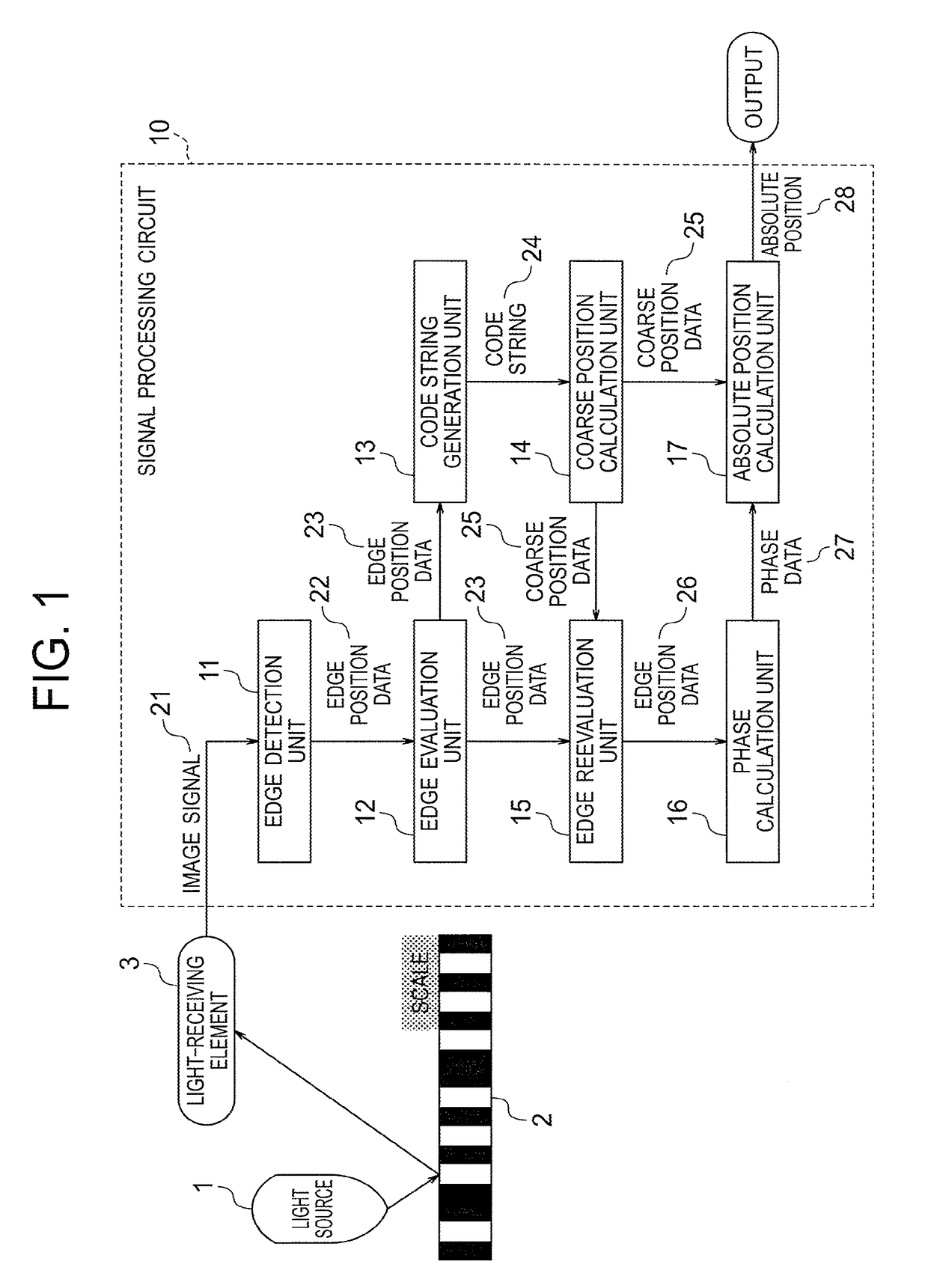
[0029]FIG. 1 is a block diagram for illustrating a configuration of a position detection device according to a first embodiment of the present invention. The position detection device illustrated in FIG. 1 includes a light source 1, a scale 2, a light-receiving element 3, and a signal processing circuit 10.

[0030]The light source 1 is configured to radiate light toward the scale 2, which has a code pattern. A specific example of the light source 1 is a light-emitting diode (LED). A specific example of the code pattern marked on the scale 2 is a pseudo-randomly coded contrast pattern. Note that, the first embodiment is described based on an exemplary case in which the scale 2 has a pseudo-random code.

[0031]The light-receiving element 3 is configured to receive the light irradiated from the light source 1 toward the scale 2, and convert the received light into an image signal 21. Further, the light-receiving element 3 is configured to output the image signal 21 obtained by conversion t...

second embodiment

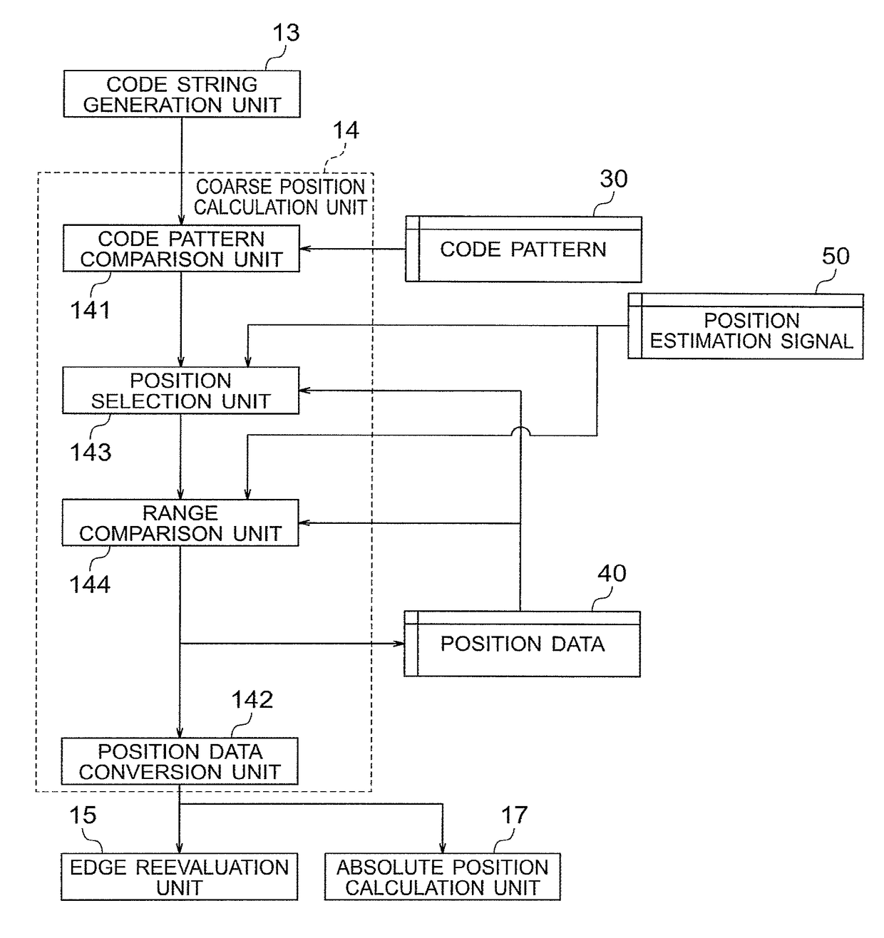
[0184]In a second embodiment of the present invention, a position detection device is described that has the same configuration as the position detection device according to the first embodiment illustrated in FIG. 1 but differs from the position detection device according to the first embodiment in the configuration of the coarse position calculation unit 14 and the processing performed by each of the edge evaluation unit 12 and the edge validity redetermination unit 153.

[0185]Note that, in the second embodiment, a description of the matters that are the same as in the first embodiment is omitted. The second embodiment is described focusing on the differences in the configuration of the coarse position calculation unit 14, and the differences in the processing performed by each of the edge evaluation unit 12 and the edge validity redetermination unit 153.

[0186]FIG. 16 is a block diagram for illustrating the configuration of the coarse position calculation unit 14 of the position de...


PUM


Abstract

To obtain a position detection device capable of detecting highly accurate and robust position by suppressing affect of error detection of an edge, provided is a configuration for performing a validity determination of edges detected by binarizing an image signal (21) converted by a light-receiving element (3) for receiving light irradiated from a light source (1) toward a scale (2) having a code pattern, and performing position detection after removing the edges determined to be invalid as edges that have been affected by foreign matter and the like among the edges on which the validity determination has been performed.

Description

BACKGROUND OF THE INVENTION[0001]1. Field of the Invention[0002]The present invention relates to a position detection device for detecting an absolute position based on an image signal converted by a light-receiving element for receiving light irradiated from a light source toward a scale having a code pattern.[0003]2. Description of the Related Art[0004]In a positioning device such as a measurement device or a servomotor, accurate position detection is essential in order to realize high-level control. An encoder is an example of a device that is widely used to perform this kind of position detection. The encoder needs to be capable of highly accurate position detection as well as have a robustness having a high resistance to foreign matter and noise.[0005]When high accuracy and a high level of robustness are required for position detection, an optical encoder is used. The optical encoder is usually configured from a light source, a scale having an equally spaced pattern or a pseudo...

Claims


Application Information

Patent Timeline
Patent Type & Authority Patents(United States)
IPC IPC(8): G06K9/62G06T7/73G06T7/13G06T7/00G06K9/03G06K9/20G06K9/46G06V10/145G06V10/44
CPCG06K9/03G06K9/2036G06K9/4604G06K9/6215G06T7/13G06T7/73G01D5/34776G06V10/145G06V10/44G06F18/22
Inventor NASU, OSAMUTAKEYAMA, HARUHIKOSASAKI, TORUNOGUCHI, TAKUYANAKAJIMA, HAJIMETATEI, YOSHINAOTAKEDA, SHIGENORIMUSHA, TAKESHIAGRAWAL, AMITTHORNTON, JAY E.
Owner MITSUBISHI ELECTRIC CORP
Why Eureka
Try Eureka