
Common inversion driving type liquid crystal display device and its driving method capable of suppressing color errors

a liquid crystal display and driving type technology, applied in the direction of instruments, static indicating devices, etc., can solve the problems of increasing manufacturing costs, reducing reliability, and difficult to connect the signal line driver and the scan line driver to the panel, so as to suppress the effect of transient phenomenon, suppressing color errors and residual dc components

Inactive Publication Date: 2008-10-07
RENESAS ELECTRONICS CORP
View PDF5 Cites 12 Cited by
  • Summary
  • Abstract
  • Description
  • Claims
  • Application Information

AI Technical Summary

Benefits of technology

This solution effectively suppresses color errors and residual DC components, improving the reliability and manufacturing efficiency of LCDs by optimizing driver connections and voltage distribution.

Problems solved by technology

However, as the capacity of the panel has been increased, it is difficult to connect the signal line driver and the scan line driver to the panel due to the narrow pitch of the scan lines and the signal lines.
In this case, however, the glass substrate of the panel becomes very large, which would increase the manufacturing cost and decrease the reliability.

Method used


Image

  • Common inversion driving type liquid crystal display device and its driving method capable of suppressing color errors
  • Common inversion driving type liquid crystal display device and its driving method capable of suppressing color errors
  • Common inversion driving type liquid crystal display device and its driving method capable of suppressing color errors

Examples


Embodiment Construction

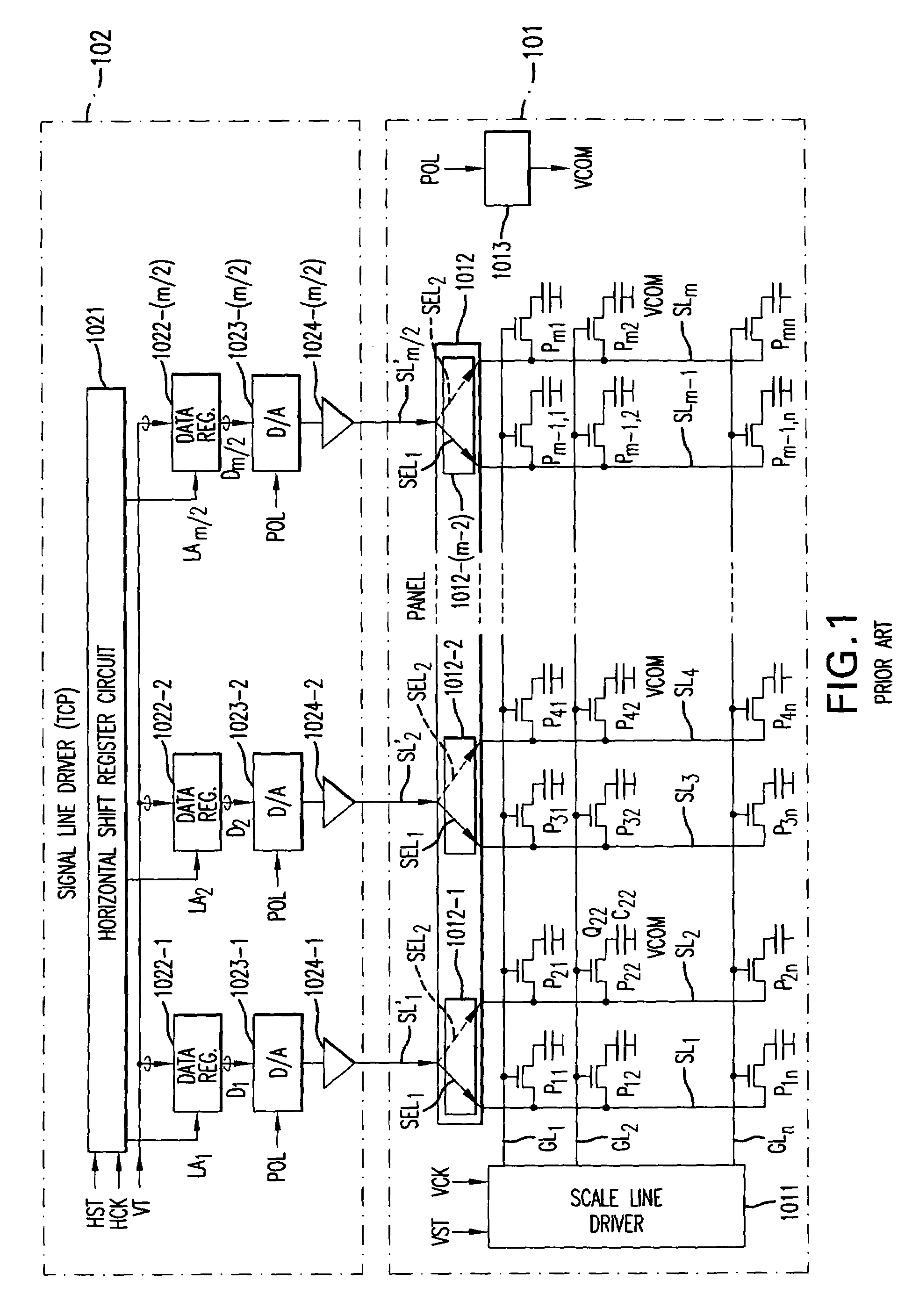
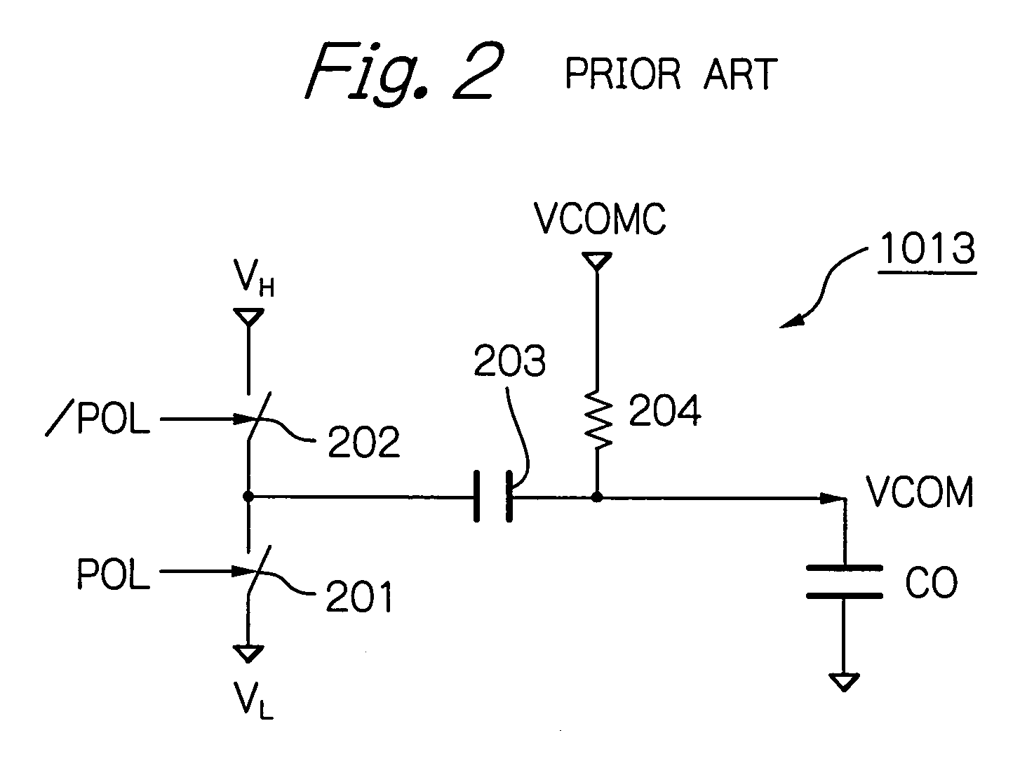
[0027]Before the description of the preferred embodiment, prior art LCD apparatuses will be explained with reference to FIGS. 1, 2, 3A, 3B, 3C, 4A, 4B, 4C, 5, 6A through 6H, and 7A through 7H.

[0028]In FIG. 1, which illustrates a first prior art LCD apparatus (see: JP-2001-109435-A), reference numeral 101 designates an m×n-dot panel formed by a polycrystalline silicon on a glass substrate by using a low temperature CVD process. The panel 101 includes m signal lines SL1, SL2, . . . , SLm, n scan lines GL1, GL2 . . . , GLn, m×n pixel units P11, P12, . . . , Pmn located at intersections between the signal lines SL1, SL2, . . . , SLm and the scan lines GL1, GL2 . . . , GLn. Each of the pixel units P11, P12, . . . , Pmn is constructed by one TFT such as Q22 and one pixel capacitor such as C22 including liquid crystal connected to the TFT Q22 and a common electrode to which a common voltage VCOM is applied. The panel 101 also includes a scan line driver 1011 which is constructed by a verti...


PUM

PropertyMeasurementUnit
voltageaaaaaaaaaa
timeaaaaaaaaaa
digital coloraaaaaaaaaa

Abstract

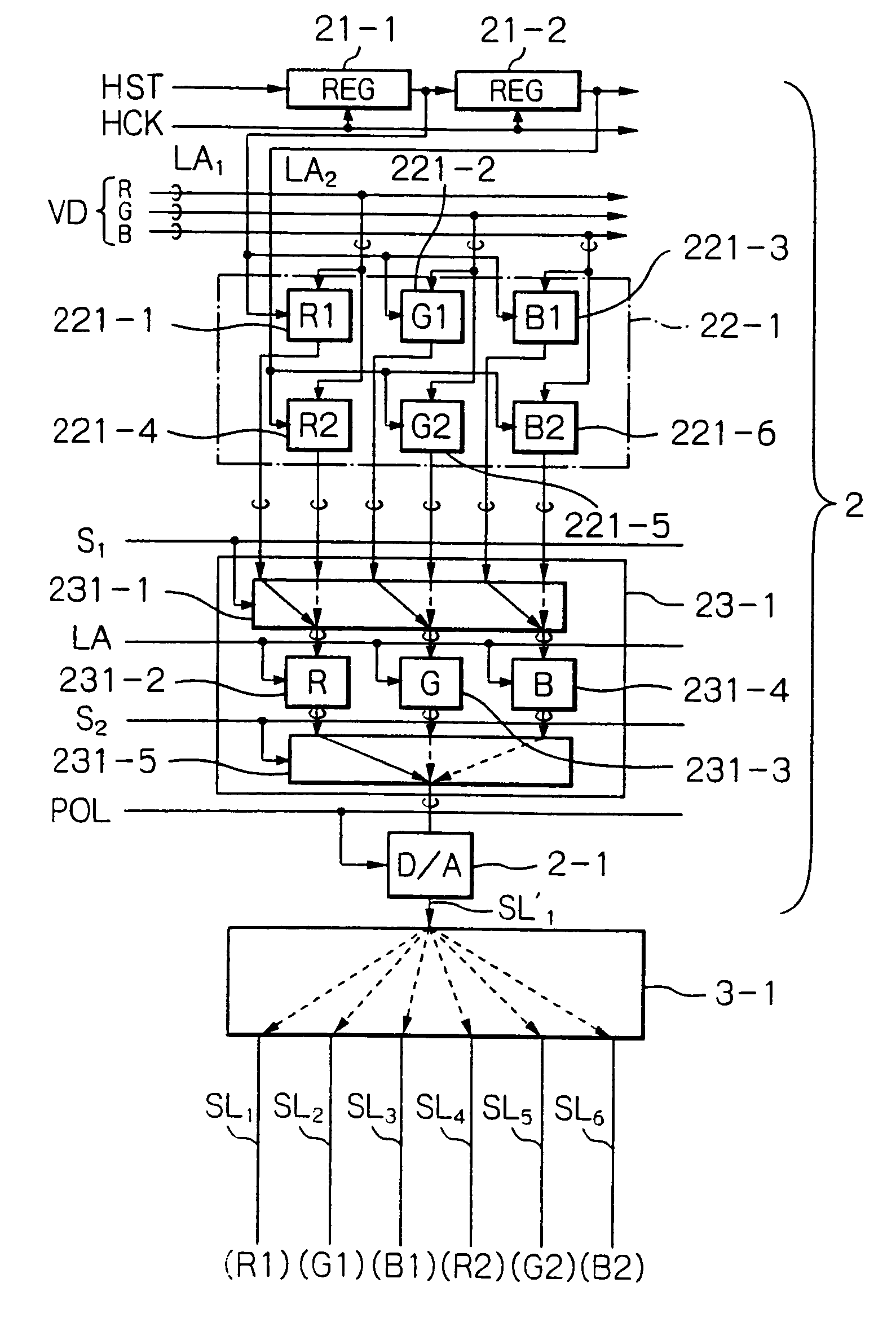
In a method for driving a common inversion type liquid crystal display apparatus including a plurality of signal lines, a plurality of scan lines, a common electrode, and a plurality of pixel units, a common voltage applied to the common electrode is inverted for every scan line. Also, digital video signals each including a plurality of digital color signals are time-divisionally received while one of the scan lines is selected. Further, a sequence of the digital video signals including the digital color signals is changed for every two consecutive frames to time-divisionally generate an output sequence of analog video signals including analog color signals, so that each of the analog color signals is placed exclusively at predetermined time slots of the output sequence. Additionally, the output sequence of the analog video signals including the analog color signals are time-divisionally supplied to the signal lines so that the analog color signals are supplied to their corresponding signal lines.

Description

BACKGROUND OF THE INVENTION[0001]1. Field of the Invention[0002]The present invention relates to a common inversion driving type liquid crystal display (LCD) device and its driving method.[0003]2. Description of the Related Art[0004]Generally, an LCD apparatus is constructed by an amorphous silicon panel including a plurality of signal lines (or data lines) arranged along a column direction, a plurality of scan lines (or gate lines) arranged along a row direction, a plurality of active pixel units each including one thin film transistor (TFT) made of amorphous silicon and one pixel capacitor located at intersections between the signal lines and the scan lines, a signal line driver formed on a flexible printed board called a tape carrier package (TCP) connected to the panel, and a scan line driver formed on another flexible printed board (TCP) connected to the panel. However, as the capacity of the panel has been increased, it is difficult to connect the signal line driver and the sc...

Claims


Application Information

Patent Timeline
Patent Type & Authority Patents(United States)
IPC IPC(8): G09G3/36G02F1/133G09G3/20
CPCG09G3/3614G09G3/3648G09G3/3688G09G2310/027G09G2310/0297G09G2320/0204G09G3/36
Inventor KATO, FUMIHIKO
Owner RENESAS ELECTRONICS CORP
Learn More