Ignition timing control device of internal combustion engine

a technology of ignition timing and control device, which is applied in the direction of machines/engines, instruments, analogue processes for specific applications, etc., can solve the problems that the retardation or advancing of ignition timing may not be performed appropriately

Active Publication Date: 2009-01-20
TOYOTA JIDOSHA KK +1
View PDF6 Cites 14 Cited by
  • Summary
  • Abstract
  • Description
  • Claims
  • Application Information

AI Technical Summary

Benefits of technology

[0013]According to the present invention, the number of times that knocking has occurred is determined based on intensity values satisfying a predetermined first condition and intensity values in an ignition cycle in which a value relating to a deviation satisfying a predetermined second condition is calculated. A value relating to a deviation is calculated to be smaller if, for example, detected waveforms include waveforms of vibration due to operation of a predetermined component (vibration of a noise component) of the internal combustion engine, compared with the case of not including them. A knock determination level is calculated by adding a product of a standard deviation and a coefficient to the median of the detected intensity values, and the number of intensity values larger than the knock determination level is determined as the number of times that knocking has occurred. Note that vibration of a noise component occurs irrespective of knocking being present or absent. Therefore, if the detected intensity values include intensity values of vibration of a noise component, the number of times that knocking has occurred may not be determined correctly. When vibrations of a noise component are caused, detected intensity values become larger. Further, in an ignition cycle in which waveforms of vibration of a noise component are detected, a value relating to a deviation is calculated to be small. Therefore, intensity values, which are larger than the first value and are in an ignition cycle in which a value relating to a deviation smaller than the second value is calculated, can be considered as intensity values of vibration of a noise component. Therefore, for example, based on intensity values satisfying a condition of smaller than the first value and intensity values in an ignition cycle in which a value relating to a deviation satisfying a condition of larger than the second value is calculated, the number of times that knocking has occurred is determined. In other words, intensity values, which are larger than the first value and are in an ignition cycle in which a value relating to a deviation smaller than the second value is calculated, are excluded from the detected intensity values, and the number of times that knocking has occurred is determined. Thereby, it is possible to determine the number of times that knocking has occurred based on intensity values considered as not intensity values of vibration of a noise component. Therefore, the number of times that knocking has occurred can be determined while suppressing influence of a noise. Consequently, it is possible to determine the number of times that knocking has occurred with high accuracy. Based on the number of times that knocking has occurred determined in this manner, ignition timing is controlled. Thereby, ignition timing of the internal combustion engine can be controlled appropriately.
[0021]According to the present invention, it is possible to control ignition timing appropriately by suppressing a noise component generated due to at least one of a piston, an injector, an intake valve and an exhaust valve.
[0027]According to the present invention, it is possible to control ignition timing appropriately by suppressing a noise component generated due to at least one of a piston, an injector, an intake valve and an exhaust valve.

Problems solved by technology

Therefore, if the detected intensity values include intensity values of vibration of a noise component, a knocking occurrence state may not be determined correctly, whereby retarding or advancing of ignition timing may not be performed appropriately.

Method used


Image

  • Ignition timing control device of internal combustion engine
  • Ignition timing control device of internal combustion engine
  • Ignition timing control device of internal combustion engine

Examples


Embodiment Construction

[0040]Hereinafter, an embodiment of the present invention will be described with reference to the drawings. In the description below, same components are denoted by same reference numerals. Their names and functions are same. Therefore, detailed description thereof will not be repeated.

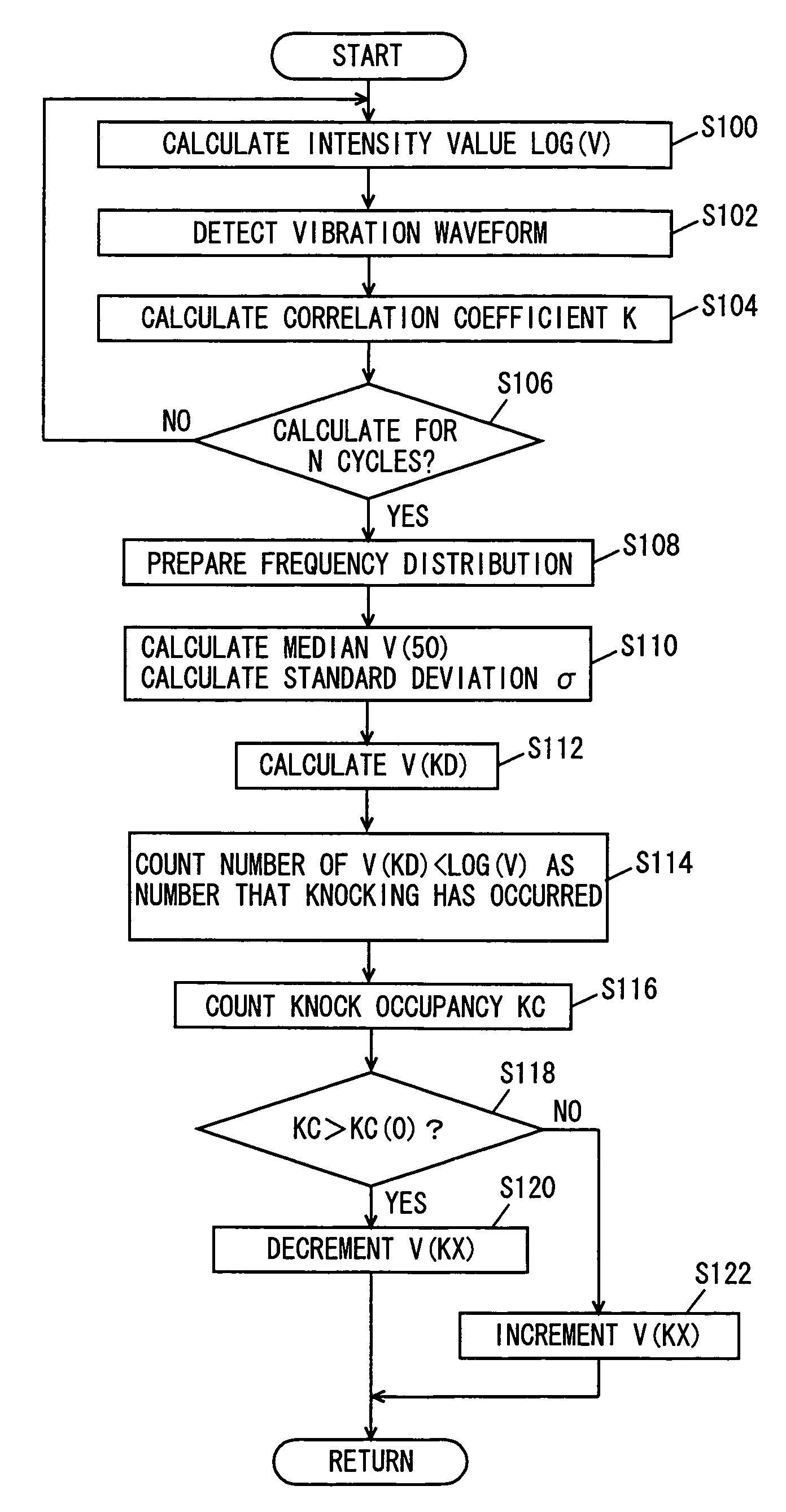
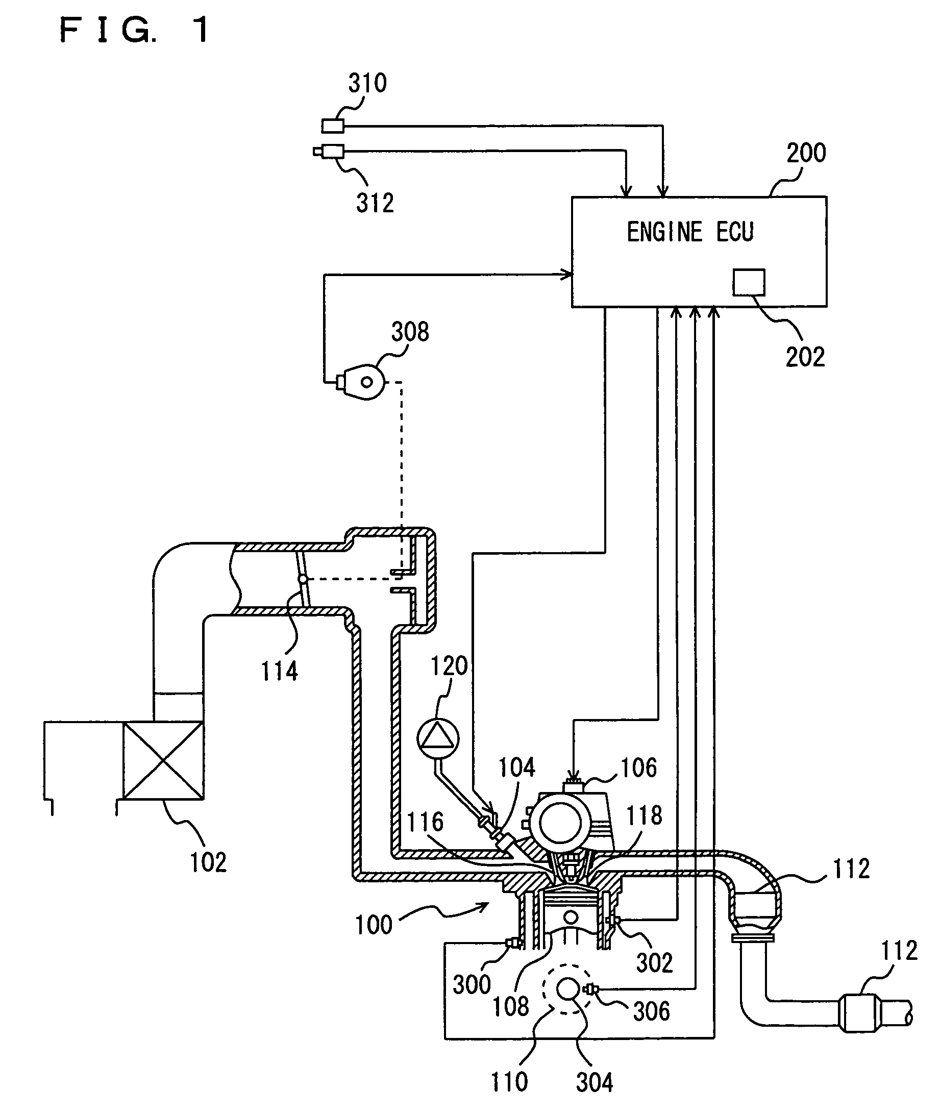
[0041]Referring to FIG. 1, an engine 100 of a vehicle mounting an ignition timing control device of an internal combustion engine according to an embodiment of the present invention will be described. The ignition timing control device of the internal combustion engine according to the present embodiment is realized by a program executed by an engine ECU (Electronic Control Unit) 200 for example.

[0042]Engine 100 is an internal combustion engine which ignites an air taken from an air cleaner 102 and an air-fuel mixture injected from an injector 104 with an ignition plug 106 in a combustion chamber and burns them. Injector 104 may be one which injects fuel into an intake manifold, or one which directly ...


PUM

PropertyMeasurementUnit
crank angleaaaaaaaaaa
frequency distributionaaaaaaaaaa
combustion pressureaaaaaaaaaa

Abstract

An engine ECU executes a program including a step of calculating intensity values LOG(V), a step of detecting vibration waveforms, a step of calculating a correlation coefficient K based on vibration waveforms, a step of preparing frequency distribution of intensity values LOG(V) smaller than a threshold V(1) and intensity values LOG(V) in an ignition cycle where correlation coefficient K is larger than a threshold K(1), a step of calculating a knock determination level V(KD) based on a median V(50) and a standard deviation σ of intensity values LOG(V), and a step of counting the number of intensity values LOG(V) larger than knock determination level V(KD) as the number of times that knocking has occurred.

Description

[0001]This nonprovisional application is based on Japanese Patent Application No. 2005-188556 filed with the Japan Patent Office on Jun. 28, 2005, the entire contents of which are hereby incorporated by reference.BACKGROUND OF THE INVENTION[0002]1. Field of the Invention[0003]The present invention relates to a technique for controlling ignition timing of an internal combustion engine, and in particular, to a technique in which a plurality of intensity values relating to the intensity of vibration of the internal combustion engine are detected, and based on the intensity values and the number (frequency) of each intensity value, ignition timing of the internal combustion engine is controlled.[0004]2. Description of the Background Art[0005]In general, a knock determination level is set by multiplying an average value of knock sensor signals with a constant K. Such a KCS (Knock Control System) involves a problem that an optimum K value changes depending on manufacturing variations or t...

Claims


Application Information

Patent Timeline
Patent Type & Authority Patents(United States)
IPC IPC(8): F02P5/00G01L23/22
CPCF02D35/027F02P5/152G01L23/225Y02T10/46Y02T10/40
Inventor KANEKO, RIHITOKASASHIMA, KENJIYOSHIHARA, MASATOMOASO, KOJISENDA, KENJIKAMIO, SHIGERUTAKEMURA, YUICHI
Owner TOYOTA JIDOSHA KK
Why Eureka
Try Eureka