Quadrature demodulator and interrogator

a demodulator and quadrilateral technology, applied in the field of quadrilateral demodulator and interrogator, can solve the problems of frequency-occurrence of incorrect reproduction of reception data due to noise, and achieve the effect of reducing the occurrence of incorrect reproduction of reception data and reliability suppressing the influence of nois

Inactive Publication Date: 2009-02-03
TOSHIBA TEC KK
View PDF2 Cites 11 Cited by
  • Summary
  • Abstract
  • Description
  • Claims
  • Application Information

AI Technical Summary

Benefits of technology

[0013]According to the present invention, there is provided a quadrature demodulator and an interrogator equipped with the quadrature demodulator, which can reliably suppress the influence of noises even if the level of the reception signal becomes low, thereby reducing an occurrence of incorrect reproduction of the reception data due to noises.

Problems solved by technology

Thus, there has been a problem that when a level of the reception signal is low, the reception signal is easily influenced by noises, and then, incorrect reproduction of the reception data due to noises frequently occurs.

Method used


Image

  • Quadrature demodulator and interrogator
  • Quadrature demodulator and interrogator
  • Quadrature demodulator and interrogator

Examples


first embodiment

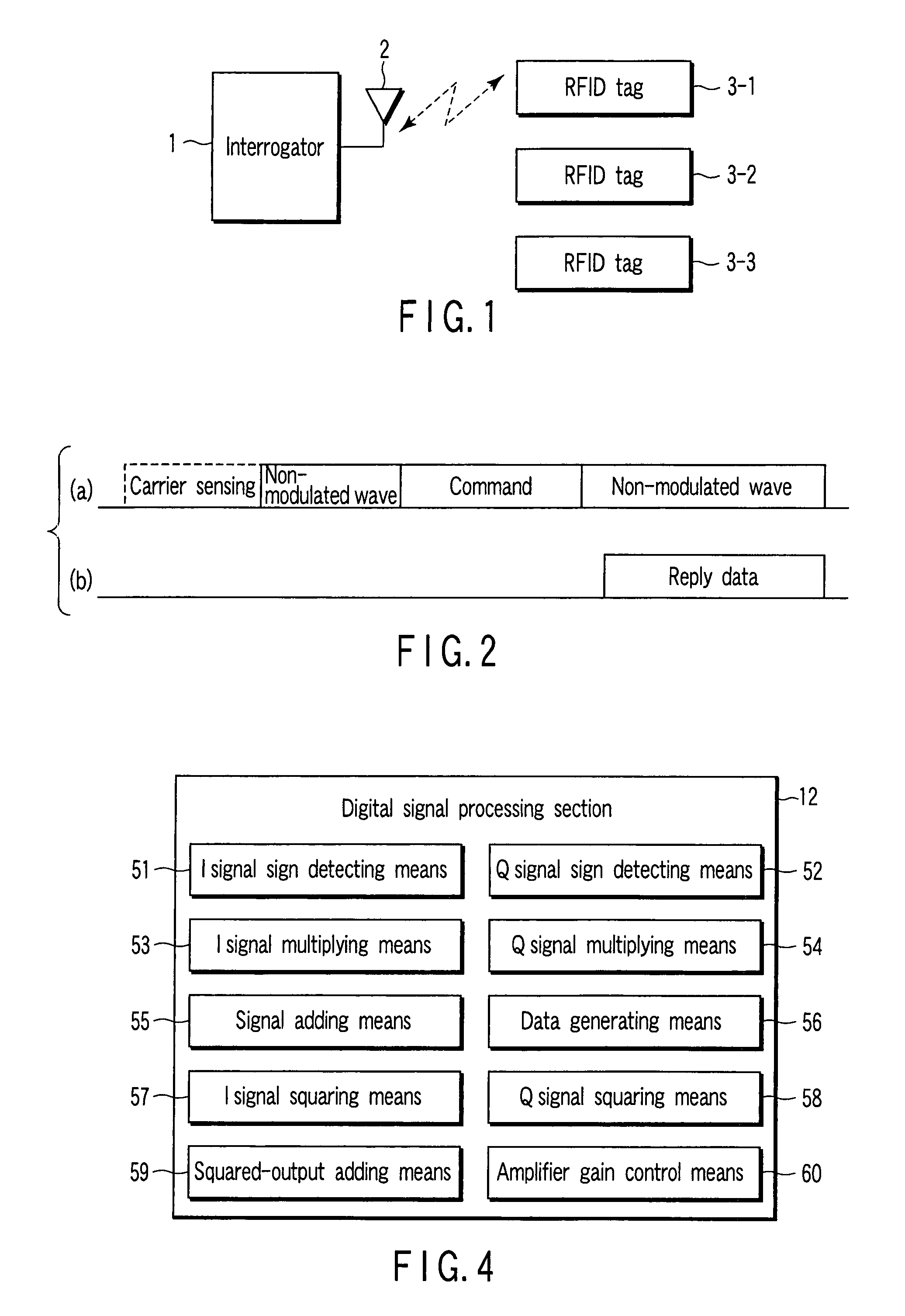
[0026]FIG. 1 is a block diagram depicting the schematic configuration of a system including an interrogator and RFID tags that serve as transponders. The interrogator 1 is equipped with an antenna 2. The antenna 2 operates to radiate a high frequency signal as a radio wave at the time of transmission and convert a received radio wave to a high frequency signal at the time of reception.

[0027]The radio wave radiated from the antenna 2 arrives at RFID tags 3-1, 3-2, and 3-3, and the respective RFID tags receive them. The RFID tags 3-1, 3-2, and 3-3 hold identification numbers specific thereto, respectively.

[0028]When the interrogator 1 transmits a signal for interrogation, the RFID tags 3-1, 3-2, and 3-3 perform an operation corresponding to the signal for interrogation. For example, in the case where the signal for interrogation includes data that only designates the identification number for the RFID tag 3-1, a reply is returned only from the RFID tag 3-1, and thus no reply is return...

second embodiment

[0068]While the foregoing first embodiment has described a mode of determining a sign of a signal while comparing an I signal and a Q signal with an offset voltage, the present embodiment describes determining a sign of a signal from data on an I signal and a Q signal, and then, reproducing reception data. Like components operating in the same manner as those of the first embodiment are designated by like reference numerals, and a detailed description thereof is omitted here.

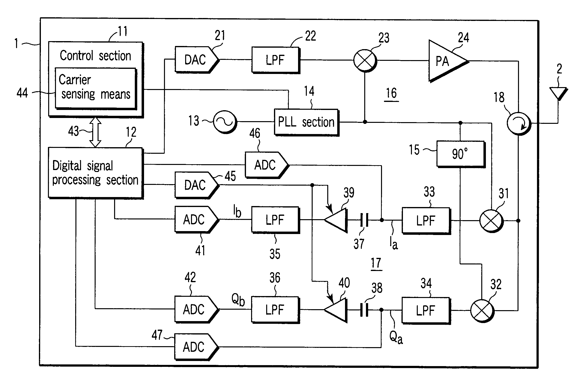
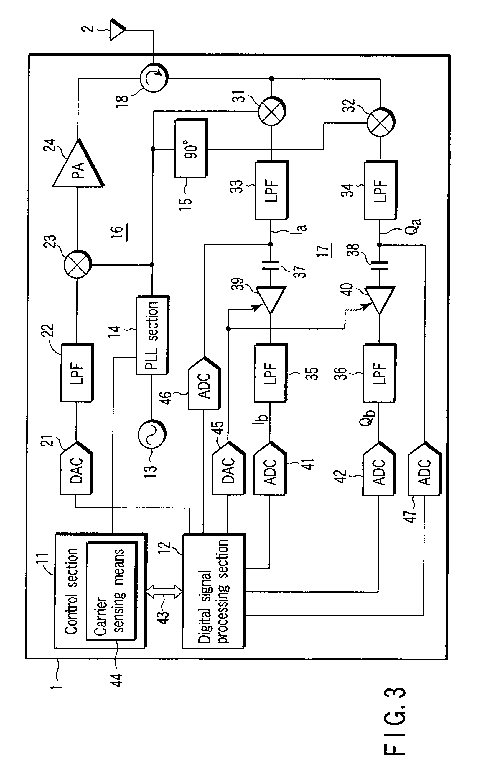
[0069]FIG. 8 is a schematic block diagram depicting the configuration of an interrogator 1. This block diagram is different from that of the first embodiment in that signals Ia and Qa output from second and third LPFs 33 and 34 of a receiving section 17 are not input to a digital signal processing section via DACs 46 and 47.

[0070]A signal Ib from a fourth LPF 35 is converted into a digital signal by a first ADC 41, and then, the converted digital signal is supplied to a digital signal processing section 121. In ...


PUM


Abstract

In a receiving section, a first mixer and a second mixer generate an I signal and a Q signal from a modulated reception signal, a local signal, and a local signal obtained by shifting a phase by 90 degrees. These I signal and Q signal are supplied to a digital signal processing section via a low path filter, a capacitor, a variable gain amplifier, and an ADC. In addition, the generated I signal and Q signal are directly supplied to the digital signal processing section. The digital signal processing section detects a sign of the I signal and a sign of the Q signal, the signals being directly input. In addition, the detected sign of the I signal is multiplied with the I signal input from the ADC, and then, the detected sign of the Q signal is multiplied with the Q signal input from the ADC, whereby the signs are commonly established in a positive state. Then, the I signal and the Q signal are added, and decoded into two-values.

Description

CROSS-REFERENCE TO RELATED APPLICATIONS[0001]This application is based upon and claims the benefit of priority from the prior Japanese Patent Application No. 2006-050679, filed Feb. 27, 2006, the entire contents of which are incorporated herein by reference.BACKGROUND OF THE INVENTION[0002]1. Field of the Invention[0003]The present invention relates to a quadrature demodulator and an interrogator equipped with the quadrature demodulator for, when a reception signal is demodulated, creating an I signal and a Q signal of a baseband.[0004]2. Description of the Related Art[0005]An interrogator is a radio communication device that makes radio communication with a transponder called a radio tag or RFID (radio frequency identification) tag. The interrogator transmits data to the RFID tag by using a modulated radio signal, and then, continuously transmits a non-modulated signal after the end of transmitting the data. In contrast, the RFID tag carries out backscatter modulation that changes ...

Claims


Application Information

Patent Timeline
Patent Type & Authority Patents(United States)
IPC IPC(8): H04L27/22H04B1/30H04B1/59H03D1/00
CPCH04L25/061H04L27/22
Inventor MUROFUSHI, NOBUOOISHI, SADATOSHI
Owner TOSHIBA TEC KK
Why Eureka
Try Eureka