Solid-state image pickup apparatus having a differential output

Inactive Publication Date: 2008-04-01
CANON KK
View PDF10 Cites 12 Cited by
  • Summary
  • Abstract
  • Description
  • Claims
  • Application Information

AI Technical Summary

Benefits of technology

[0036]An object of the present invention is to provide an image pick

Problems solved by technology

As in the driving method described with reference to FIG. 6, the inverting input terminal of the differential amplifier circuit 51 is in the state of high impedance (floating) at the timing when the signal is read out to the horizontal output line, and hence is easily affected by the disturbance noise generated due to the

Method used


Image

  • Solid-state image pickup apparatus having a differential output
  • Solid-state image pickup apparatus having a differential output
  • Solid-state image pickup apparatus having a differential output

Examples


Example

First Embodiment

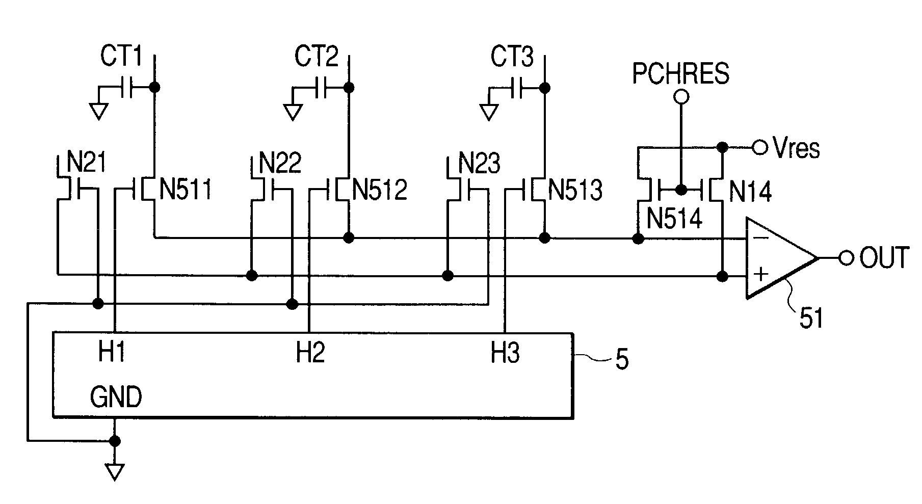
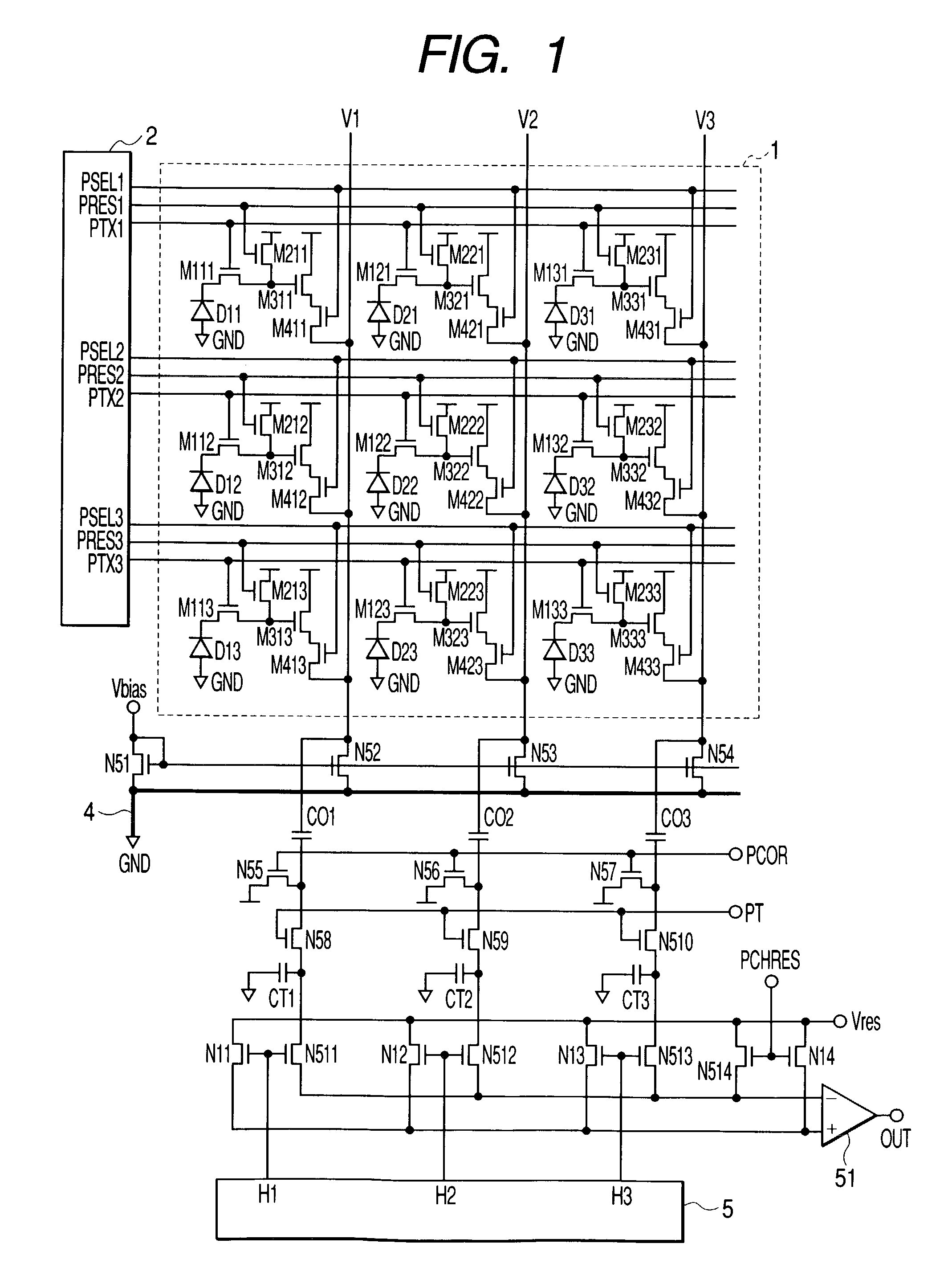
[0056]FIG. 1 is an equivalent circuit diagram showing a configuration of a solid-state image pickup device according to a first embodiment of the present invention. In FIG. 1, a pixel unit 1, an input MOS transistor N51, load MOS transistors N52 to N54, clamp capacitors C01 to C03, clamp switches N55 to N57, transfer switches N58 to N510, and signal holding capacitors CT1 to CT3 are the same in configuration as those shown in FIG. 5. By the way, in FIG. 1, the same constituent elements as those shown in FIG. 5 are denoted by the same reference numerals.

[0057]The capacitors CT1 to CT3 for temporarily holding signals are connected to an inverting input terminal (horizontal output line) of a differential amplifier circuit 51 through horizontal transfer switches N511 to N513, respectively, and the horizontal output line is connected to a reset voltage Vres through a reset switch N514.

[0058]Gates of the horizontal transfer switches N511 to N513 are respectively connected ...

Example

Second Embodiment

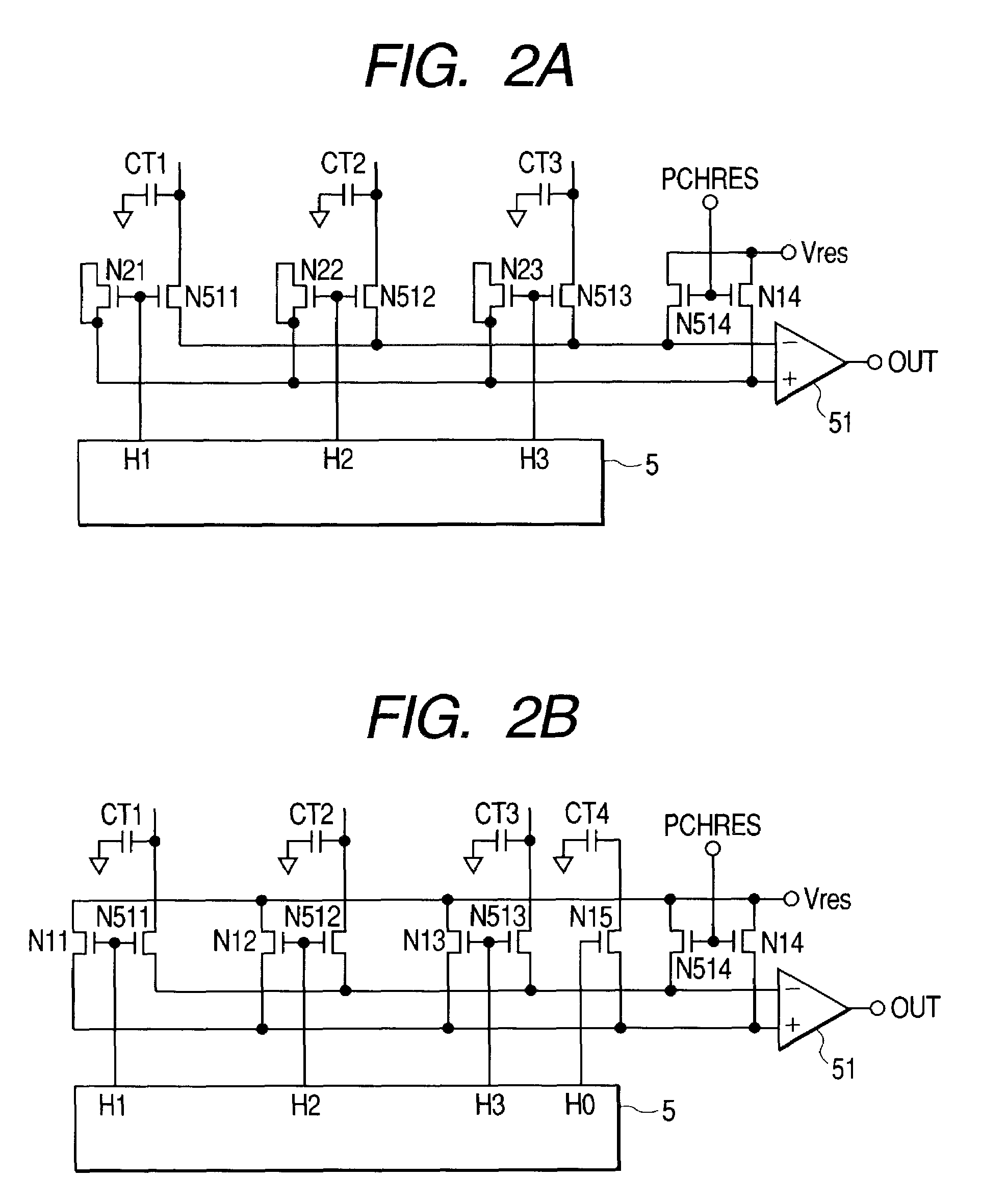
[0071]FIG. 2A is an equivalent circuit diagram showing a configuration of a part of a solid-state image pickup device according to a second embodiment of the present invention. In FIG. 2A, there is shown a part which is arranged on the lower side in the drawing than the signal holding capacitors CT1 to CT3 shown in FIG. 1, and hence other constituent elements are the same in configuration as those shown in FIG. 1. By the way, in FIG. 2A, the same constituent elements are denoted by the same reference numerals as those shown in FIG. 1.

[0072]Similarly to FIG. 1, the capacitors CT1 to CT3 for temporarily holding signals are connected to the inverting input terminal (horizontal output line) of the differential amplifier circuit 51 through the horizontal transfer switches N511 to N513, respectively, and the horizontal output line is connected to the reset voltage Vres through the reset switch N514.

[0073]Gates of the horizontal transfer switches N511 to N513 are respectiv...

Example

Third Embodiment

[0103]FIG. 3 is an equivalent circuit diagram showing a configuration of a part of a solid-state image pickup device according to a third embodiment of the present invention. In FIG. 3, there is shown a part that is arranged on the lower side in the drawing than the signal holding capacitors CT1 to CT3 shown in FIG. 1, and hence other constituent elements are the same in configuration as those shown in FIG. 1. By the way, in FIG. 3, the same constituent elements are denoted by the same reference numerals as those shown in FIG. 1.

[0104]The capacitors CT1 to CT3 for temporarily holding signals are connected to the inverting input terminal (horizontal output line) of the differential amplifier circuit 51 through the horizontal transfer switches N511 to N513, respectively, and the horizontal output line is connected to the reset voltage Vres through the reset switch N514.

[0105]Gates of the horizontal transfer switches N511 to N513 are respectively connected to the signal...


PUM


Abstract

An image pickup apparatus including: a plurality of photoelectric conversion elements for photoelectrically converting light from an object, a first output line to which signals from the plurality of photoelectric conversion elements are successively outputted, a plurality of first switches connected to the first output line to output the signals from the plurality of photoelectric conversion elements to the first output line, a second output line to which a reference signal is supplied, a plurality of second switches connected to the second output line to supply the reference signal to the second output line, a scanning circuit which controls the plurality of first switches and the plurality of second switches, and a differential circuit which obtains a difference between the signal from the first output line and the signal from the second output line.

Description

BACKGROUND OF THE INVENTION[0001]1. Field of the Invention[0002]The present invention relates to an image pickup apparatus for picking up an image of an object.[0003]2. Related Background Art[0004]In recent years, for the promotion of high resolution, the cell size reduction of photoelectric conversion devices employing the miniaturization process has been vigorously carried out, while an amplification type solid-state image pickup device which is capable of amplifying a photoelectric conversion signal to output the resultant signal thus amplified has received much attention in order to avoid the reduction in magnitude of photoelectric conversion output signals or the like due to the miniaturization process.[0005]As for such amplification type solid-state image pickup devices, there are devices of a MOS type, an AMI type, a CMD type, a BASIS type, and the like. Of those, the MOS type solid-state image pickup device is constructed such that optical carriers generated in a photodiode ...

Claims


Application Information

Patent Timeline
IPC IPC(8): H04N5/217H04N3/14H04N5/335H01L27/146H01L27/14H04N5/357H04N5/369H04N5/374H04N5/376
CPCH04N5/378H04N5/3577H04N25/617H04N25/75
Inventor SAKURAI, KATSUHITOKOIZUMI, TORUHIYAMA, HIROKIFUJIMURA, MASARU
Owner CANON KK
Why Eureka
Try Eureka