

Communication connector
- Summary
- Abstract
- Description
- Claims
- Application Information
AI Technical Summary
Benefits of technology
Problems solved by technology
Method used
Image

Examples
Example
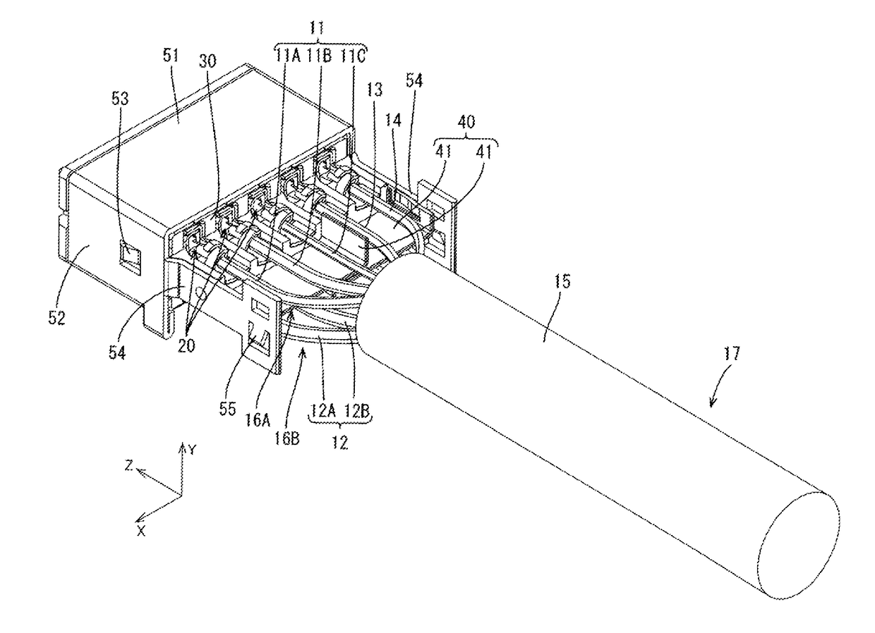
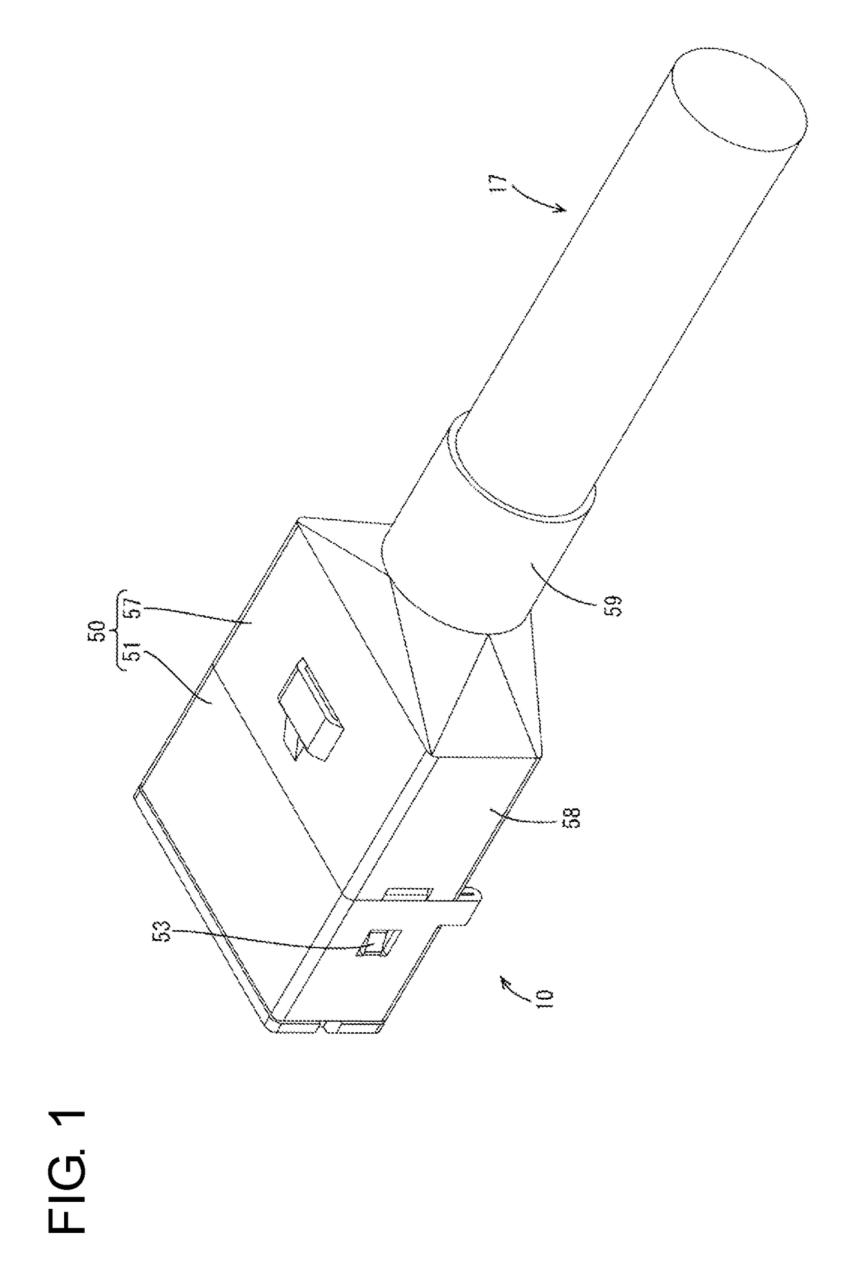
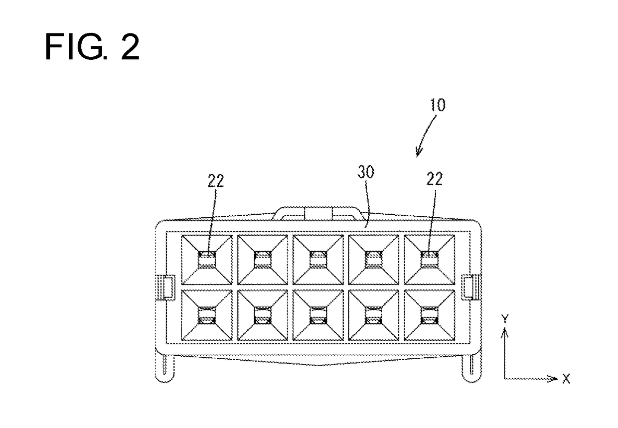
[0102]A first embodiment is described with reference to FIGS. 1 to 13. A communication connector 10 is installed in a vehicle such as an electric vehicle or hybrid vehicle and arranged in a wired communication path between an in-vehicle electric component (navigation system, ETC system, monitor, etc.) in the vehicle and an external device (camera, etc.) or between in-vehicle electric components. In the following description, a vertical direction (Y-axis) and a lateral direction (X-axis) are based on directions of FIG. 2, and a left side and a right side of FIG. 4 are referred to as a front side and a rear side concerning a front-rear direction (Z-axis).
[0103]The communication connector 10 of this embodiment includes, as shown in FIG. 3, a shielded cable 17 having a plurality of (ten in this embodiment) wires 11,12, 13 and 14. The wires 11 are composed of two sets of first wires 11A to 11C, and the wires 12 are composed of one set of second wires 12, 12B. Terminals 20 are connected t...
Example
[0130]A second embodiment of the invention is described with reference to FIGS. 14 to 25. The same components as in the first embodiment are denoted by the same reference signs and not described.
[0131]Although the shield 40 is formed from two partition plates 41, 41 in the first embodiment, a shield 70 formed by applying punching and bending to one metal plate material is used in a communication connector of the second embodiment.
[0132]As shown in FIGS. 20 and 21, an extending portion 62 extending rearward while having a smaller thickness than a housing 61 is formed with groove-like placing portions 37 arranged on the upper and lower surfaces of the extending portion 62 such that wire connecting portions 23 of respective terminals 20 can be placed thereon. Three press-fit holes 63A to 63C are formed at intervals on the rear end surface of the extending portion 62, with the middle press-fit hole 62B being wider than the other two press-fit holes 63A, 63C.
[0133]The shield 70 is made o...
Example
[0137]A third embodiment of the present invention is described with reference to FIGS. 26 to 31.
[0138]In the third embodiment, wire connecting portions 82 of terminals 81 are crimped and connected to wires 11 to 14 as shown in FIG. 26. The same components as in the above embodiments are denoted by the same reference signs and not described.
[0139]The wire connecting portion 82 of the terminal 81 includes two wire barrel portions 83 and two insulation barrel portions 84 standing from both side edges of a bottom plate. The wire barrel portions 83 are crimped to a conductor exposed at an end part of the wire 11 to 14, and the insulation barrel portions 84 are crimped to hold an insulation coating of the wire 11 to 14.
[0140]An extending portion 88 extends rearward while having a smaller thickness than a housing 86. The extending portion 88 is formed with a plurality of placing portions 87 arranged on the upper and lower surfaces of the extending portion 88 such that the wire connecting p...
PUM
 Abstract
Description
Claims
Application Information