Transmitter

a technology of transmitters and receivers, applied in the field of transmitters, can solve problems such as errors in propagation path estimation

Inactive Publication Date: 2009-12-24
SHARP KK
View PDF15 Cites 0 Cited by
  • Summary
  • Abstract
  • Description
  • Claims
  • Application Information

AI Technical Summary

Benefits of technology

[0035]The transmitter of the present invention is a transmitter employing an OFDMA system which uses a frequency band that is constituted by a plurality of subchannels having a phase rotating portion which gives a same phase rotation amount to each group configured with a plurality of consecutive subcarriers modulated by data or a known signal in a portion or all of the subchannels, a rotation amount determining portion which sets a phase rotation for each antenna set or each transmitter, and a scheduling portion which sorts a data to a subchannel and determines an existence of the phase rotation.
[0019]Here, a description shall be given for the case of multi-carrier transmission being performed, and a delay of half of the symbol being added by the phase rotation described below between the transmission antennas 1a, 1b of FIG. 16. Also, diversity by the soft combining method shall be described for the case of being used between the transmitting antenna 1a and the transmitting antenna 1b. Here, for the time being only the signals transmitted from the transmitting antenna 1a and the transmitting antenna 1b shall be considered. Here, the soft combining method is a method of suppressing the interference component while increasing the signal component of the receiver by transmitting the same signal that is generated from the same data at the same timing from transmitters arranged in two sectors to the same receiver.
[0035]The transmitter of the present invention is a transmitter employing an OFDMA system which uses a frequency band that is constituted by a plurality of subchannels having a phase rotating portion which gives a same phase rotation amount to each group configured with a plurality of consecutive subcarriers modulated by data or a known signal in a portion or all of the subchannels, a rotation amount determining portion which sets a phase rotation for each antenna set or each transmitter, and a scheduling portion which sorts a data to a subchannel and determines an existence of the phase rotation.

Problems solved by technology

However, in the case of applying the CDT diversity to the transmitting antennas between sectors, since the orthogonality between orthogonal codes is lost, when attempting to separate and estimate the propagation paths between the transmitting antenna and receiving antennas of each sector using the symbols for propagation path estimation, there is the risk of an error occurring in the propagation path estimation result.

Method used


Image

  • Transmitter
  • Transmitter
  • Transmitter

Examples


first embodiment

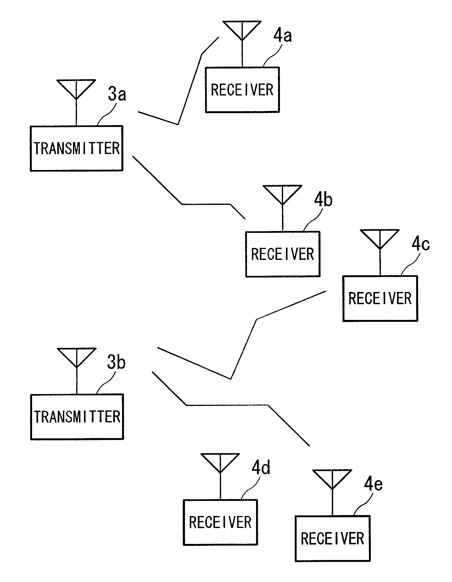
[0079]The first embodiment of the present invention will be described first. The present embodiment shows an example using two differing transmitters that use OFDMA and performing communication with some receivers. FIG. 1A is a schematic diagram of the case of transmitters communicating with receivers. During the time that the OFDMA frame that is the object of the description being transmitted, the receivers 4a to 4c perform communication with the transmitter 3a. Also, the receivers 4b to 4e perform communication with the transmitter 3b. That is, the receivers 4b and 4c combine and receive the same signals from both transmitters 3a and 3b by soft combining.

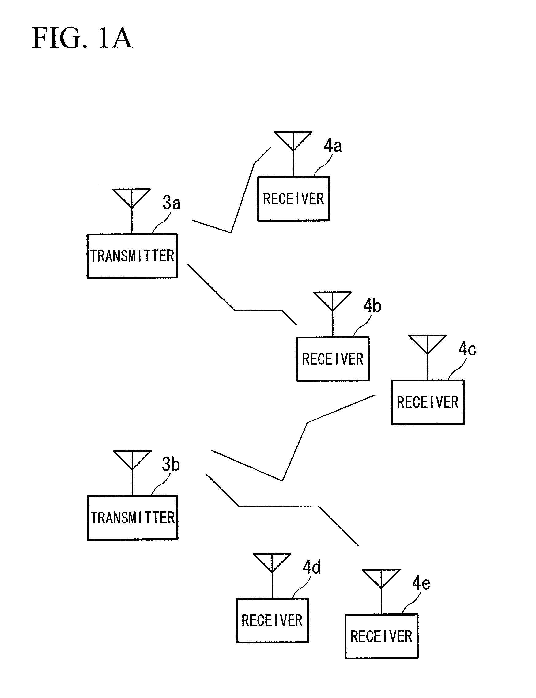
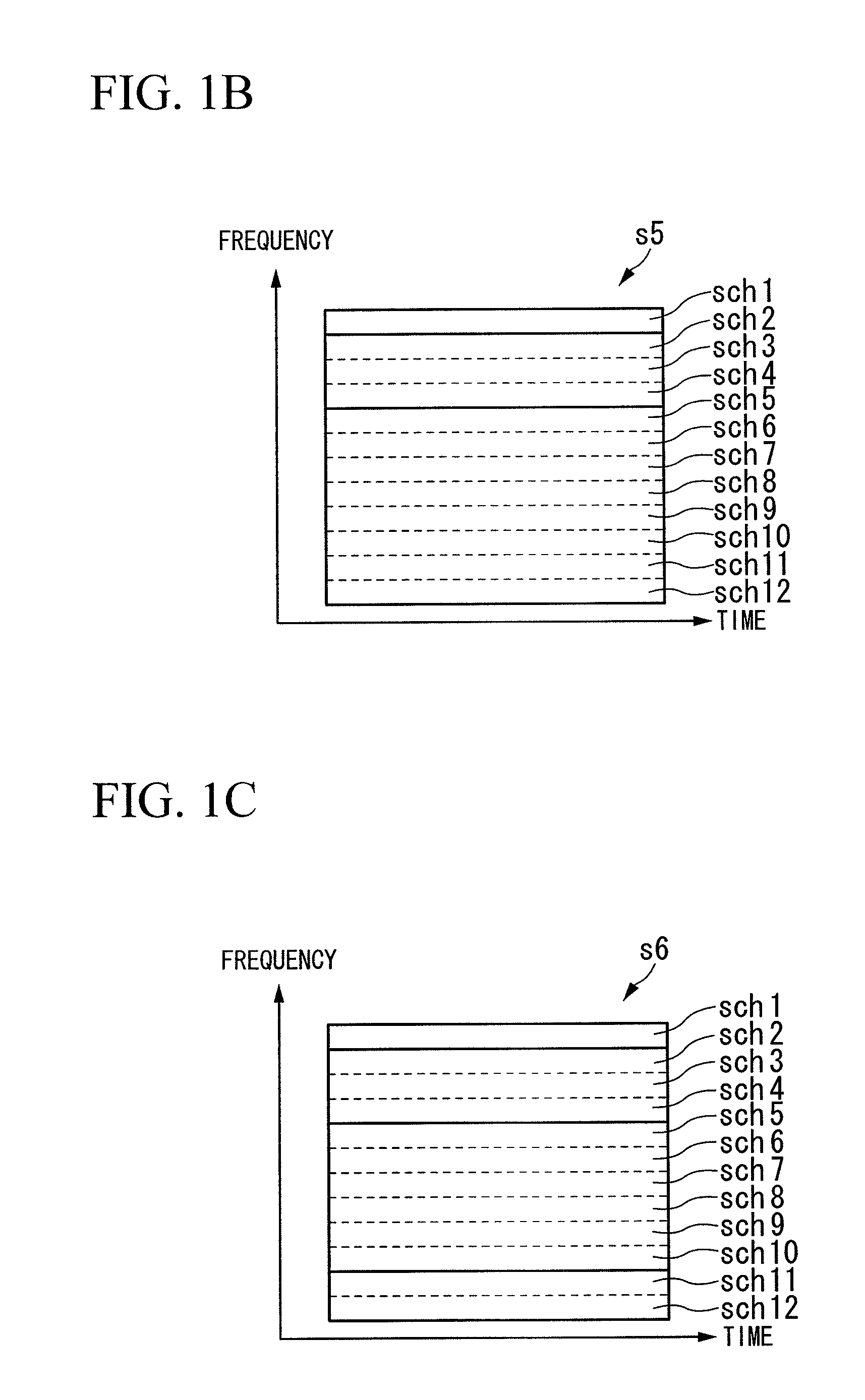
[0080]FIG. 1B and FIG. 1C are drawings that show the constitution of the signals s5 and s6 that are transmitted from the transmitters 3a and 3b. In these drawings, the vertical axis represents frequency while the horizontal axis represents time. Here, the drawings show the case of the signals s5 and s6 each being constituted from ...

second embodiment

[0136]Next, a second embodiment of the present invention will be described. It is one that allows further simplification of the constitution of the receiver with respect to the first embodiment of the present invention.

[0137]FIG. 9 is a diagram that shows the constitution of a subcarrier for propagation path estimation in the second embodiment of the present invention. In this embodiment, the subcarrier for propagation path estimation, which is a subcarrier in which symbols for propagation path estimation are arranged, is allocated at every other subcarrier. A subcarrier in which a subcarrier for propagation path estimation is not allocated is used for communication of control signals (SA1 to SA384, SB1 to SB384). Also, specific known symbols (P1 to P384) are used for the symbols for propagation path estimation, and orthogonal codes (1, 1, 1, 1), (1, 1, −1, −1) are respectively multiplied by the known symbols in the transmitters 3a, 3b.

[0138]FIG. 10 is a block diagram that shows th...

third embodiment

[0152]Next, a third embodiment of the present invention will be described. Although limitations to the orthogonal code used were not added in the first embodiment and the second embodiment, the present embodiment will describe the case of adding limitations to the orthogonal code used to enable a receiver that moves between transmitters to rapidly perform handover.

[0153]In the OFDM communication system of the present embodiment, by repeatedly allocating the code C1 to all of the subcarriers and performing 256 sample rotations, (1, j, −1, −j) repeatedly appears at all of the subcarriers. This is made code C12. Also, by similarly rotating 512 times, it becomes (1, −1, 1, −1), and this is made code C13. Also, for 768 rotations, it becomes (1, −j, j, −1), and this is made code C14.

[0154]Also, when C1=C11, C11 to C14 are all in an orthogonal relationship. The case of using these codes in the present embodiment shall be described.

[0155]In the latter of the examples of constituting the sup...


PUM


Abstract

A transmitter employing an OFDM system, having a phase rotating portion which gives a same phase rotation amount to each group configured with a plurality of consecutive subcarriers modulated by data or a known signal, a rotation amount determining portion which sets a phase rotation for each antenna set or each transmitter; and, and an allocating portion which allocates a plurality of groups to a receiver.

Description

[0001]This application is a Divisional of co-pending application Ser. No. 12 / 091,430 filed on Apr. 24, 2008, which is a National Phase of PCT / JP2006 / 321563 filed on Oct. 27, 2006, and for which priority is claimed under 35 U.S.C. § 120; and these applications claim priority of Application No. JP2005-314429 filed in Japan on Oct. 28, 2005 under 35 U.S.C. § 119; the entire contents of all are hereby incorporated by reference.TECHNICAL FIELD[0002]The present invention relates to a transmitter employing an orthogonal frequency division multiplexing (OFDM) system.[0003]Priority is claimed on Japanese Patent Application No. 2005-314429, filed Oct. 28, 2005, the content of which is incorporated herein by reference.BACKGROUND ART[0004]In recent years, multi-carrier transmission has been proposed that uses cyclic delay transmit (CDT) diversity that simultaneously performs transmission from a transmitter that is provided with a plurality of transmission antennas while adding a (cyclic) delay ...

Claims


Application Information

Patent Timeline
Patent Type & Authority Applications(United States)
IPC IPC(8): H04L27/28
CPCH04B7/0671H04L5/0016H04L5/0023H04L27/2647H04L27/2602H04L27/2634H04L25/0204H04L27/26362
Inventor HAMAGUCHI, YASUHIROIMAMURA, KIMIHIKO
Owner SHARP KK
Why Eureka
Try Eureka