Multimode optical fiber
a multi-mode optical fiber and optical fiber technology, applied in the field of multi-mode optical fiber, can solve problems such as the decrease of manufacturing yield, and achieve the effect of improving the manufacturing ease of the refractive index profil
- Summary
- Abstract
- Description
- Claims
- Application Information
AI Technical Summary
Benefits of technology
Problems solved by technology
Method used
Image

Examples
first embodiment
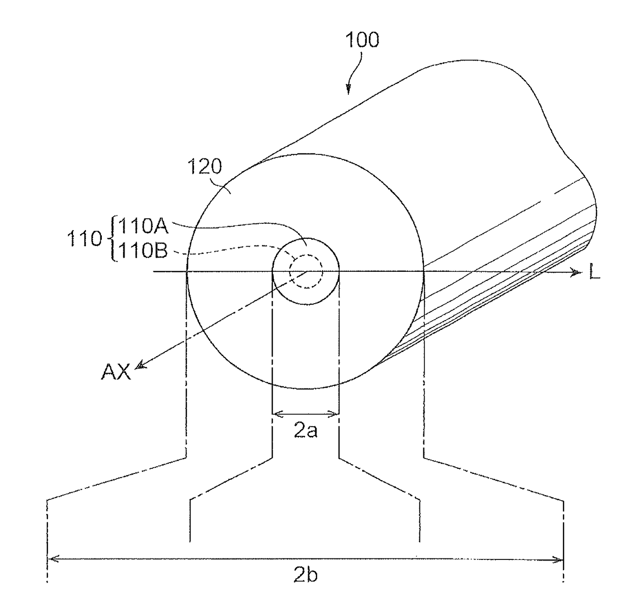
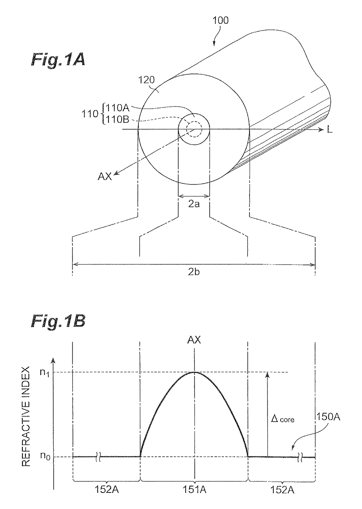
[0052]The following will describe the bandwidth evaluation of the GI-MMF of the first embodiment, using FIG. 4 and FIGS. 6A to 6C. The GI-MMF of the first embodiment is configured by doping the whole region of the core with Ge as a base dopant and doping a part of the core with P. The GI-MMF of the first embodiment has the same cross-sectional structure as the structure shown in FIG. 1A and has the refractive index profile 150A shown in FIG. 1B.
[0053]Specifically, FIG. 4 is the refractive index profile for showing a specific sectional structure of the GI-MMF of the first embodiment. In FIG. 4, the refractive index profile 150A indicates the GI refractive index profile conforming to the α-profile, which results from doping with Ge and P, and the refractive index profile 150AP the refractive index profile resulting from partial doping with P.
[0054]The GI-MMF of the first embodiment has the core 110 and the cladding 120 and the core 110 is comprised of an inside region 110A and an outs...
second embodiment
[0060]FIG. 5 is a refractive index profile for showing the cross-sectional structure of the GI-MMF according to the second embodiment and FIGS. 7A to 7C are drawings for explaining the evaluation result of the bandwidth characteristic in the GI-MMF of the second embodiment. The GI-MMF of the second embodiment, just as in the example of the first embodiment, is also configured by doping the whole region of the core with Ge as a base dopant and doping a part of the core with P. Furthermore, the GI-MMF of the second embodiment also has the same cross-sectional structure as the structure shown in FIG. 1A and has the refractive index profile 150A shown in FIG. 1B.
[0061]Specifically, FIG. 5 is the refractive index profile for showing a specific sectional structure of the GI-MMF of the second embodiment. In FIG. 5, the refractive index profile 150A indicates the GI refractive index profile conforming to the α-profile, which results from doping with Ge and P, and the refractive index profil...
third embodiment
[0069]The foregoing first and second embodiments had the configuration wherein the core 110 was partially doped with P, while the third and fourth embodiments have the configuration wherein the core is partially doped with F, instead of P. Specifically, FIG. 8 is a refractive index profile for showing the cross-sectional structure of the GI-MMF according to the third embodiment and FIGS. 10A to 10C are drawings for explaining the evaluation result of the bandwidth characteristic in the GI-MMF of the third embodiment. The GI-MMF of the third embodiment is configured by doping the whole region of the core with Ge as a base dopant and doping a part of the core with F. Furthermore, the GI-MMF of the third embodiment also has the same cross-sectional structure as the structure shown in FIG. 1A and has the refractive index profile 150A shown in FIG. 1B.
[0070]Specifically, FIG. 8 is the refractive index profile for showing a specific sectional structure of the GI-MMF of the third embodimen...
PUM
| Property | Measurement | Unit |
|---|---|---|
| refractive index | aaaaa | aaaaa |
| refractive index | aaaaa | aaaaa |
| refractive index | aaaaa | aaaaa |
Abstract
Description
Claims
Application Information
 - R&D
- Intellectual Property
- Life Sciences
- Materials
- Tech Scout
- Unparalleled Data Quality
- Higher Quality Content
- 60% Fewer Hallucinations
Browse by: Latest US Patents, China's latest patents, Technical Efficacy Thesaurus, Application Domain, Technology Topic, Popular Technical Reports.
© 2025 PatSnap. All rights reserved.Legal|Privacy policy|Modern Slavery Act Transparency Statement|Sitemap|About US| Contact US: help@patsnap.com