Liquid supply unit having filter

a technology of liquid supply unit and filter, which is applied in the direction of printing, etc., can solve the problems of filter desirably catching soft contaminants, soft contaminants end up passing through the mesh, and soft contaminants end up passing through the filter

Active Publication Date: 2017-11-07
SEIKO EPSON CORP
View PDF14 Cites 0 Cited by
  • Summary
  • Abstract
  • Description
  • Claims
  • Application Information

AI Technical Summary

Benefits of technology

[0009]With this application example, the first filter and the second filter are each constituted by a plurality of fibers laminated in the flow direction of the liquid, and differ from each other in coarseness. According to this configuration, even if contaminants get into the openings in the first filter, the contaminants are readily prevented from advancing by the plurality of fibers laminated in the flow direction of the liquid. Also, because the second filter is downstream of the first filter, contaminants that get through the first filter are readily caught by the second filter. Therefore, with this liquid supply unit, the outflow of contaminants is readily reduced.

Problems solved by technology

The filter desirably catches soft contaminants as well as hard contaminants.
Such soft contaminants may pass through filter mesh even if the outer shape of the contaminants is larger than the mesh.
One reason is that even if contaminants having a larger outer shape than the filter mesh are initially caught in the filter, soft contaminants end up passing through the mesh due to the contaminants gradually changing shape.
Thus, with existing liquid supply units, there is a problem in that it is difficult to reduce the outflow of contaminants.
Also, because the second filter is downstream of the first filter, contaminants that get through the first filter are readily caught by the second filter.
Contaminants are thereby readily caught by the filter.

Method used


Image

  • Liquid supply unit having filter
  • Liquid supply unit having filter
  • Liquid supply unit having filter

Examples


Embodiment Construction

[0051]Embodiments will be described with reference to the drawings, taking a liquid jet system as an example. Note that, in the drawings, the scale of constituent elements and members may differ from actual size, in order to show the respective elements at a recognizable size.

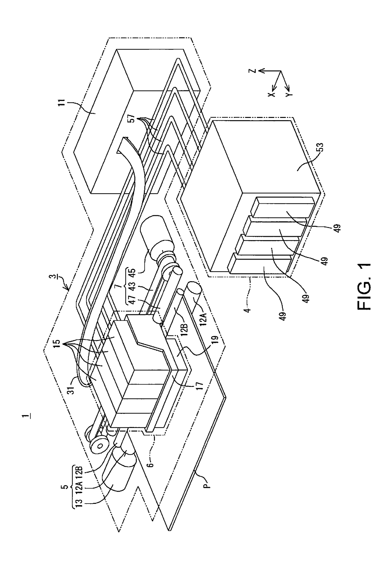
[0052]A liquid jet system 1 in the present embodiment has, as shown in FIG. 1, a printer 3, which is an example of a liquid jet apparatus, and an ink supply apparatus 4, which is an example of a liquid supply apparatus. The printer 3 has a conveyance apparatus 5, a recorder 6, a move apparatus 7 and a controller 11. Note that XYZ axes, which are coordinate axes orthogonal to each other, are given in FIG. 1. The XYZ axes are also given as necessary in the following diagrams. In the present embodiment, the liquid jet system 1 is in a use state when disposed in a horizontal plane (XY plane) defined by the X-axis and the Y-axis. The Z-axis is orthogonal to the horizontal plane. In the use state of the liquid jet sy...


PUM


Abstract

A liquid supply unit configured to supply a liquid to a liquid inlet of a liquid jet apparatus. The liquid supply unit includes a liquid housing part configured to house a liquid, a liquid outlet configured to draw the liquid from inside the liquid housing part to outside the liquid housing part, and a filter provided upstream of the liquid outlet in a channel of the liquid that is drawn from inside the liquid housing part to outside the liquid housing part via the liquid outlet. The filter includes a first filter and a second filter that are constituted by a plurality of fibers laminated in a flow direction of the liquid. The first filter is provided upstream of the second filter in the channel of the liquid, and the first filter and the second filter differ in coarseness.

Description

[0001]Priority is claimed under 35 U.S.C. §119 to Japanese Application No. 2015-088167 filed on Apr. 23, 2015 which is hereby incorporated by reference in its entirety.BACKGROUND[0002]1. Technical Field[0003]The present invention relates to liquid supply units and the like.[0004]2. Related Art[0005]One example of a liquid supply unit is an ink cartridge that is applied to an inkjet recording apparatus. Ink cartridges in which a bag-like pack housed inside a case is provided with a built-in filter capable of filtering ink inside the pack are heretofore known (refer to, for example, JP-A-2014-233947).[0006]The filter desirably catches soft contaminants as well as hard contaminants. There are some soft contaminants that readily change shape such as gel-like contaminants, for example. Such soft contaminants may pass through filter mesh even if the outer shape of the contaminants is larger than the mesh. One reason is that even if contaminants having a larger outer shape than the filter ...

Claims


Application Information

Patent Timeline
Patent Type & Authority Patents(United States)
IPC IPC(8): B41J2/175
CPCB41J2/17563B41J2/17513B41J2002/17516B41J2/1752
Inventor AOKI, YUJIKARASAWA, MASAHIROHIRATA, KAZUYUKI
Owner SEIKO EPSON CORP
Why Eureka
Try Eureka