Imaging device
a technology of a camera and an imaging device, which is applied in the direction of instruments, camera body details, inductances, etc., can solve the problems of wear and tear, and limit the life of the power transfer system
- Summary
- Abstract
- Description
- Claims
- Application Information
AI Technical Summary
Problems solved by technology
Method used
Image

Examples
first exemplary embodiment
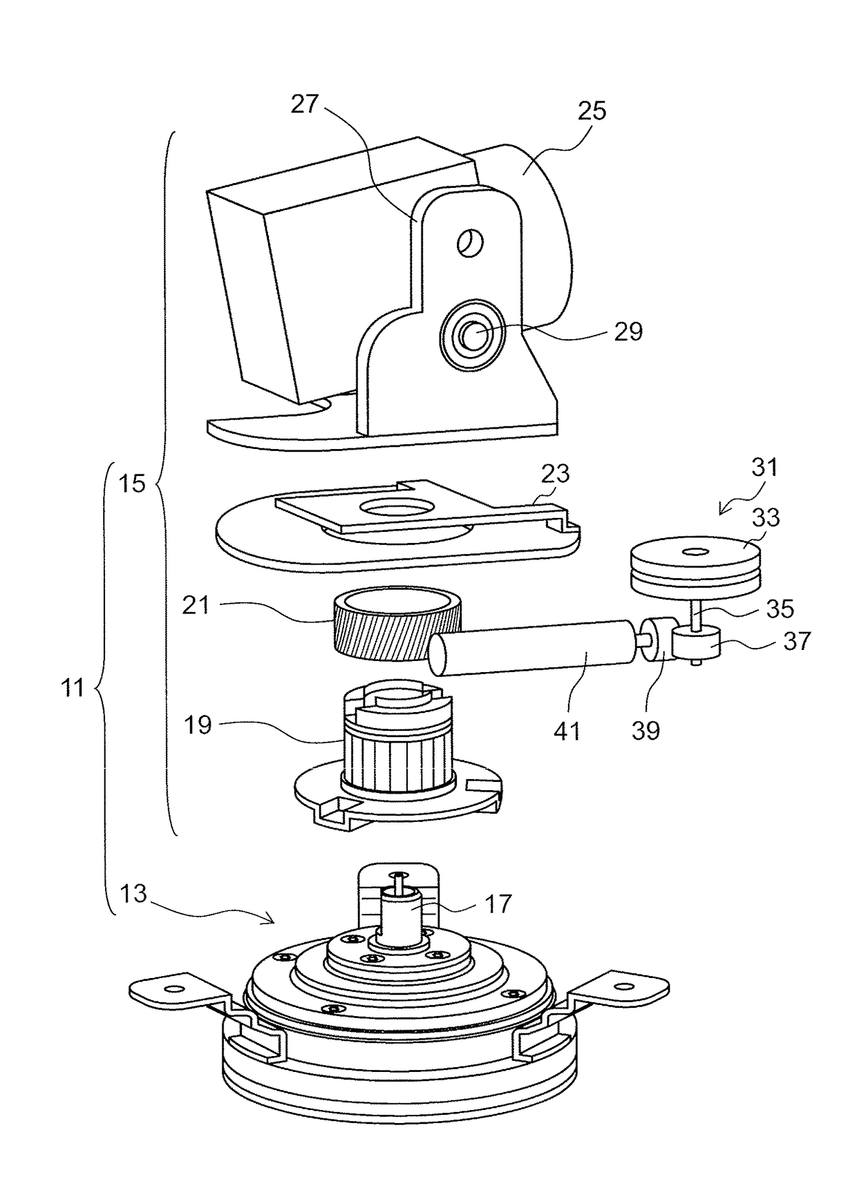
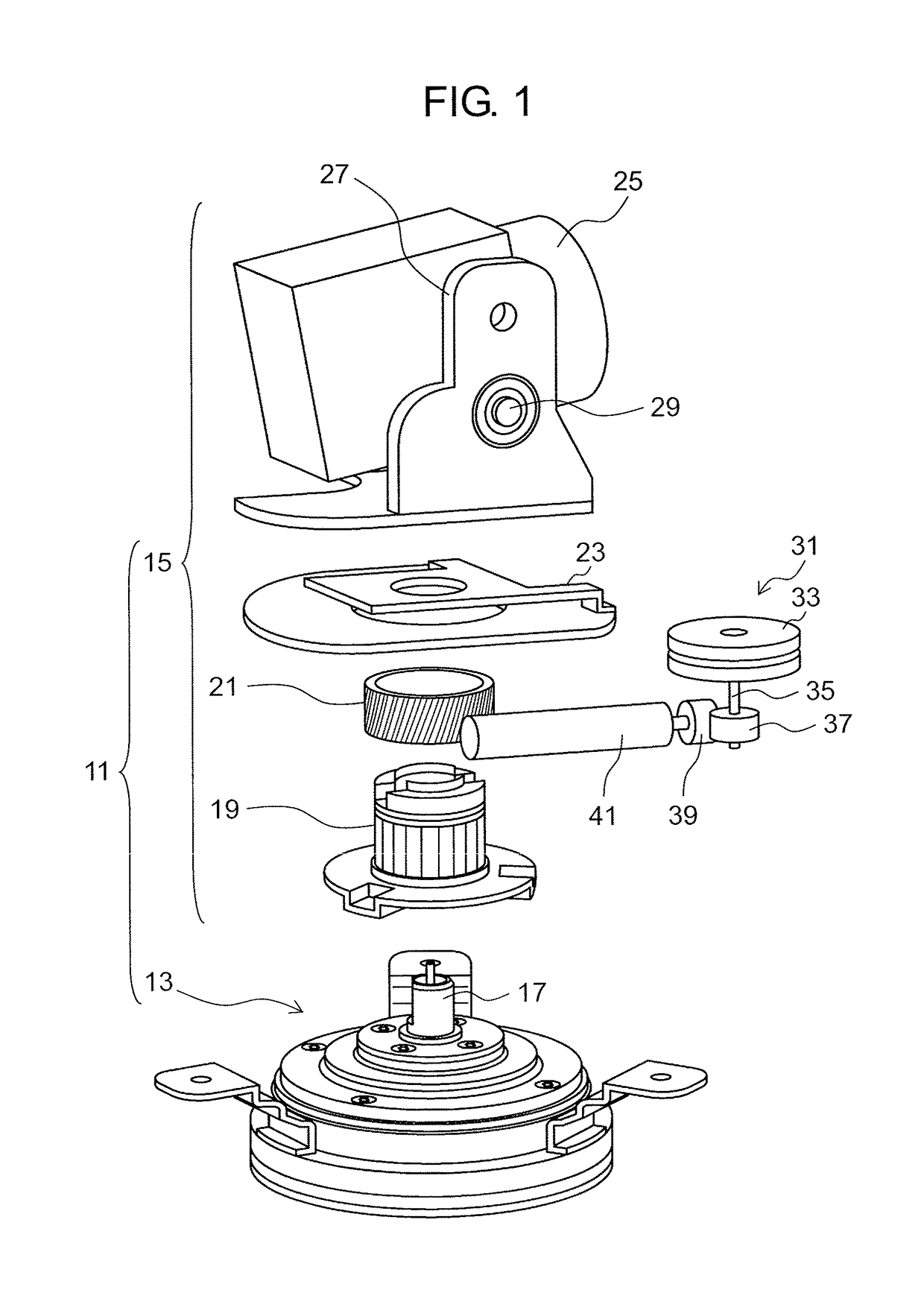
[0024]FIG. 1 is an exploded perspective view of monitoring camera 11 according to a first exemplary embodiment. Monitoring camera 11 illustrated in FIG. 1 is configured to include contactless power transmission rotating mechanism 13 and rotating unit 15. Contactless power transmission rotating mechanism 13 is fixed to a camera pedestal (not illustrated) with a main body base (not illustrated) as a device main body side interposed therebetween. Contactless power transmission rotating mechanism 13 fixed to the device main body side is connected to rotating unit 15 by shaft 17.
[0025]Rotating unit 15 has rotating shaft 19, worm wheel 21, camera bracket 23, and camera 25 as one example of an imaging unit. Shaft 17 of contactless power transmission rotating mechanism 13 is connected to rotating shaft 19 in a manner not allowing relative rotation. Worm wheel 21 is coaxially fixed to rotating shaft 19. Camera bracket 23 is fixed to rotating shaft 19. Camera bracket 23 supports camera 25. Ca...
second exemplary embodiment
[0064]Next, monitoring camera 11 of a second exemplary embodiment will be described.
[0065]FIG. 12 is a schematic view of contactless power transmission rotating mechanism 127 of monitoring camera 11 according to the second exemplary embodiment. FIG. 13 is a schematic diagram separating a camera side flange 135 side and a device main body side flange 137 side of FIG. 12. FIG. 14 is an exploded schematic view of the device main body side flange 137 side of FIG. 13. The same configurations as the members or parts illustrated in FIG. 1 to FIG. 11 will be designated by the same reference signs, and duplicate descriptions thereof will not be provided.
[0066]In monitoring camera 11 according to the second exemplary embodiment, contactless power transmission rotating mechanism 127 has a different bearing from contactless power transmission rotating mechanism 13 of the first exemplary embodiment. That is, the bearing of contactless power transmission rotating mechanism 127 of monitoring camer...
PUM
 Abstract
Description
Claims
Application Information
 - R&D
- Intellectual Property
- Life Sciences
- Materials
- Tech Scout
- Unparalleled Data Quality
- Higher Quality Content
- 60% Fewer Hallucinations
Browse by: Latest US Patents, China's latest patents, Technical Efficacy Thesaurus, Application Domain, Technology Topic, Popular Technical Reports.
© 2025 PatSnap. All rights reserved.Legal|Privacy policy|Modern Slavery Act Transparency Statement|Sitemap|About US| Contact US: help@patsnap.com