Flow control element and covered drinking cup

a technology of flow control and drinking cup, which is applied in the direction of rigid containers, packaging, thin material handling, etc., can solve the problems of difficult manufacturing, assembly and cleaning of container parts

Inactive Publication Date: 2001-01-16
CREDIT SUISSE FIRST BOSTON AS ADMINISTATIVE AGENT
View PDF96 Cites 104 Cited by
  • Summary
  • Abstract
  • Description
  • Claims
  • Application Information

AI Technical Summary

Benefits of technology

In a preferred embodiment, the control element includes a pair of shoulders that assist in maintaining the control element in place even during impact.

Problems solved by technology

Further, the number of the parts involved makes such containers difficult to manufacture, assemble and clean.

Method used


Image

  • Flow control element and covered drinking cup
  • Flow control element and covered drinking cup
  • Flow control element and covered drinking cup

Examples


Embodiment Construction

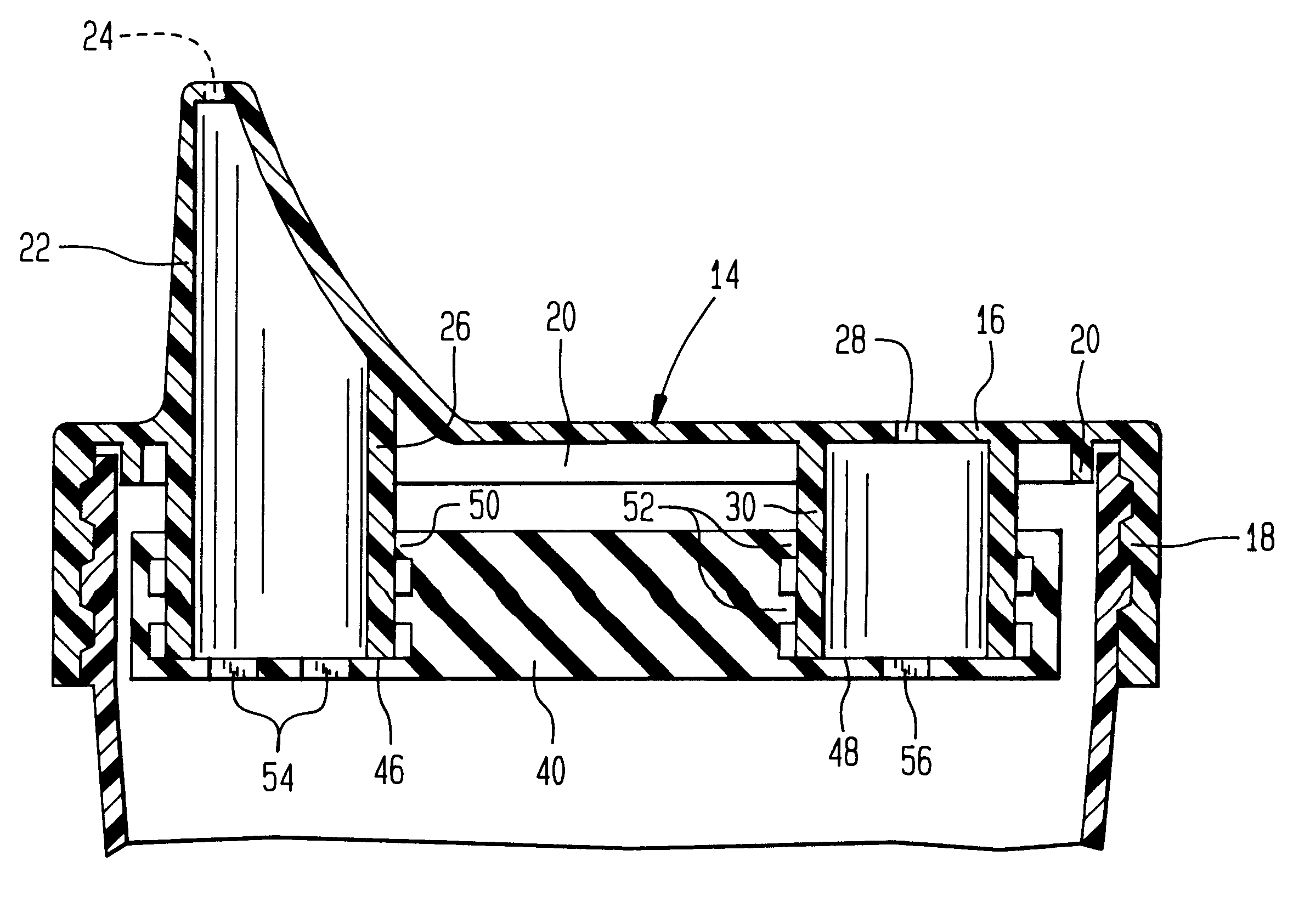
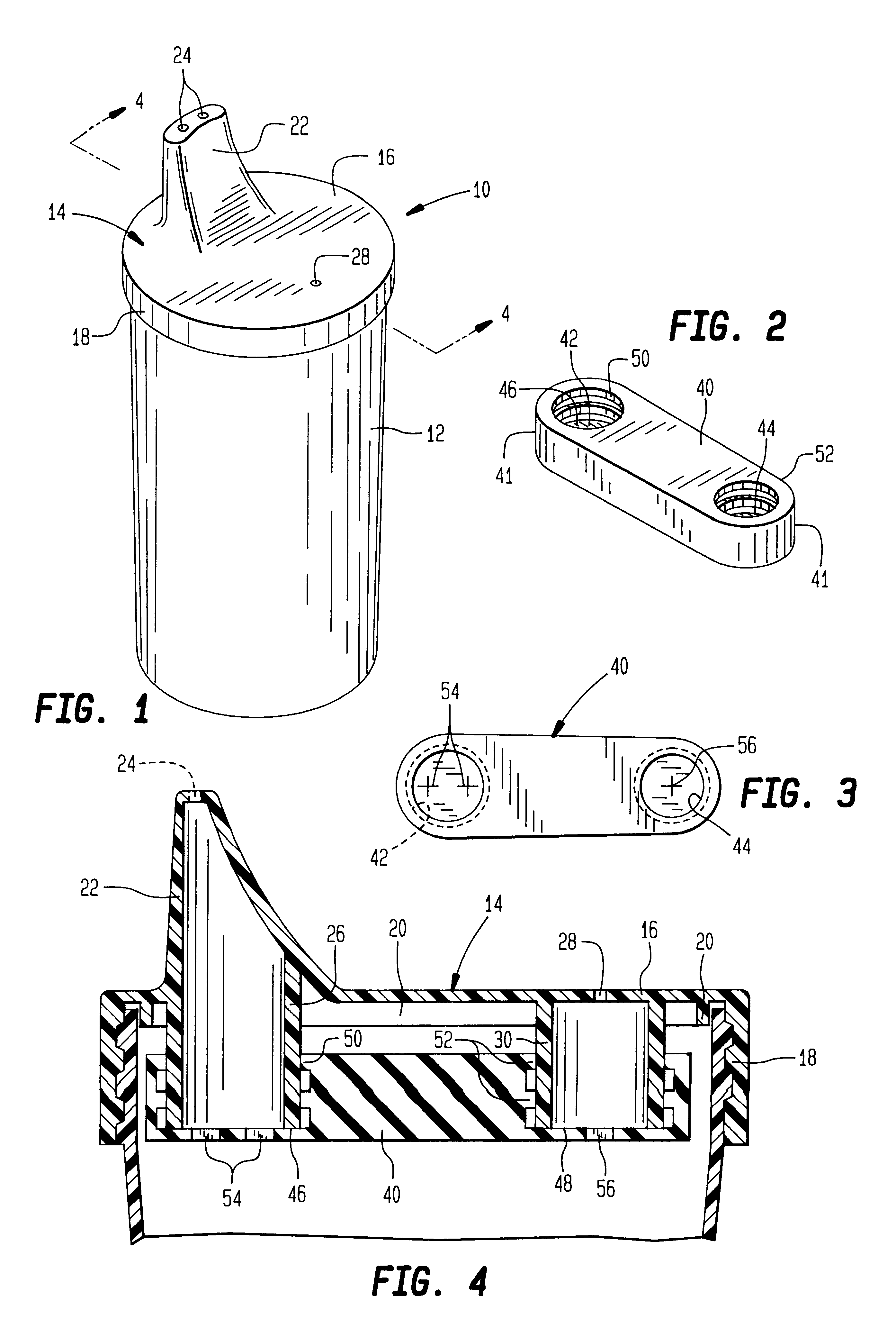
Referring to the drawings and, in particular, FIG. 1, a drinking cup that embodies the invention is generally represented by reference numeral 10. The drinking cup 10 comprises a cup-shaped container 12 having a cover 14 that may be screwed on to the top of the container by cooperant threads shown in FIG. 4. The cover 14 comprises a top wall 16 and a depending downward or side wall 18 formed with interior threads that engage exterior threads about the mouth of the container 12 as described.

Just inside the downward wall 18, the cover 14 may be provided with a short annular wall 20. Also, an O-ring (not shown) may be disposed in between the annular wall 20 and the side wall 18 of the cover 14. The O-ring may be compressed to form a liquid sealing joint between the cover 14 and the container 12.

One side of the top wall 16 is provided with a drinking spout 22 which has dispensing openings 24 at its distal end. Formed unnaturally with the cover 14 and extending downward from the spout 22...


PUM


Abstract

A drinking cup has a cover which is formed with a drinking spout at one side and a vent at the other. Elements extend down from under the spout and the vent. A flow control element is provided and made of elastomeric material having a pair of spaced cavities on one side, each cavity having a floor at the bottom thereof. The cavities receive in frictional engagement respectively the lower ends of the elements. This engagement supports the flow control element with the floor of each cavity in sealed relation to its element. Each floor has a passage which is normally closed but opens on the occurrence of a pressure differential on opposite sides of the floor.

Description

FIELD OF THE INVENTIONThis invention relates to a covered drinking cup of the type often used by infants and children as a training cup because it safeguards against spills and provides liquid flow through a nipple-like spout. More specifically, this invention relates to covered drinking cups that provide a leak-proof flow of the liquid and venting of the head space as liquid is withdrawn.BACKGROUND OF THE INVENTIONIn the past nursing bottles and cups for dispensing milk and other liquids to infants and children have often been in the form of vented covered containers. For instance, U.S. Pat. No. 2,372,281 to Jordan, which issued on Mar. 27, 1945, has a cover that provides a nipple on one side having flow-regulating means and a vent on the other side also having flow-regulating means. By adjusting the two flow-regulating means, the user can comfortably draw liquid from the nipple. As the liquid is withdrawn, air moves in through the vent to replace the withdrawn liquid and prevent n...

Claims


Application Information

Patent Timeline
Patent Type & Authority Patents(United States)
IPC IPC(8): A47G19/22
CPCA47G19/2272Y10S215/902Y10S215/07Y10T137/86332Y10T137/7843
Inventor MORANO, EMANUEL P.
Owner CREDIT SUISSE FIRST BOSTON AS ADMINISTATIVE AGENT
Why Eureka
Try Eureka