
Light source unit, projection apparatus, and projection method
a technology of projection apparatus and light source unit, which is applied in the direction of static indicating device, picture reproducer, instruments, etc., can solve the problem of reducing the luminous efficiency of fluorescent substances, and achieve the effect of increasing the luminous efficiency
Patent Information
- Authority / Receiving Office
- US · United States
- Patent Type
- Applications(United States)
- Current Assignee / Owner
- Publication Date
- 2011-03-31
Smart Images
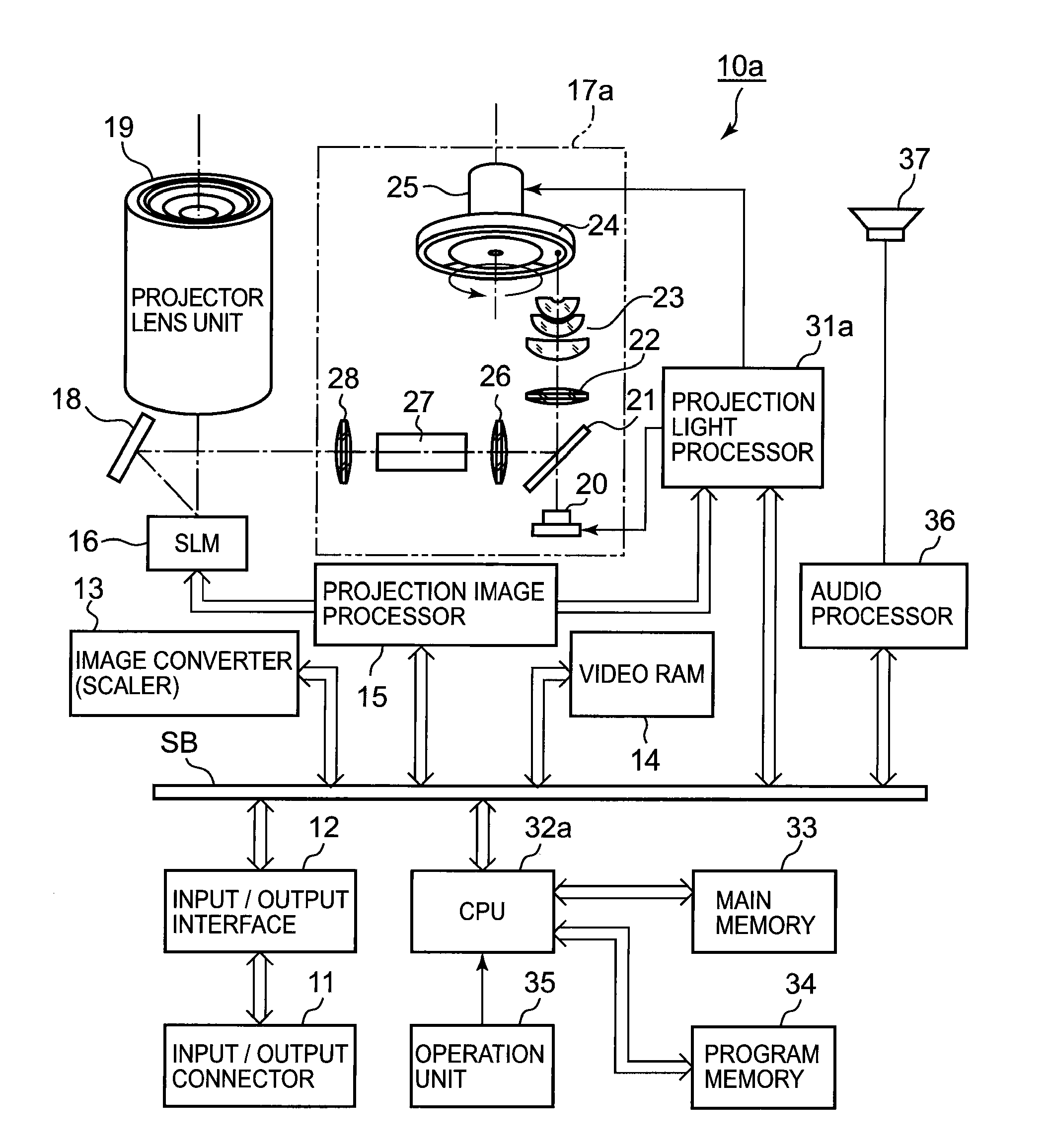
Figure 1 
Figure 2 
Figure 3
Abstract
Description
CROSS-REFERENCE TO RELATED APPLICATIONS
[0001] This application is based upon and claims the benefit of priority from prior Japanese Patent Application No. 2009-223333, filed Sep. 28, 2009, the entire contents of which are incorporated herein by reference.BACKGROUND OF THE INVENTION
[0002] 1. Field of the Invention
[0003] The present invention relates to a light source unit, a projection apparatus, and a projection method suitable for a projector or the like.
[0004] 2. Description of the Related Art
[0005] Jpn. Pat. Appln. KOKAI Publication No. 2004-341105 (hereinafter, Patent Document 1), for example, discloses a technique including a light-emitting diode or semiconductor laser to emit ultraviolet light, and a color wheel which has a fluorescent layer formed on the back side for emitting visible light corresponding to each of red, green, and blue light by radiating ultraviolet light and has a visible light reflection film formed on the front side close to a light source, having characteristi...
Examples
first embodiment
[0027]A first embodiment applied to a DLP (a registered trademark) type data projector will be described with reference to the drawings.
[0028]FIG. 1 is a block diagram showing a schematic functional configuration of electronic circuits provided in a data projector 10a according to the first embodiment.
[0029]A reference number 11 denotes an input / output connector, which includes a pin-jack (RCA) type video input terminal, D-sub 15 type RGB input terminal, and Universal Serial Bus (USB) connector, for example.
[0030]Image signals of various standards input to the input / output connector 11 are applied to an image converter 13 through an input / output interface (I / F) 12 and a system bus SB.
[0031]The image converter 13 converts the input image signal into a predetermined format suitable for projection, writes the image signal into a video RAM 14 or a buffer memory for display if necessary, reads the written image signal, and transmits the read image signal to a projection image processor 1...
second embodiment
[0071]A second embodiment applied to a DLP (a registered trademark) type data projector will be described with reference to the drawings.
[0072]FIG. 4 is a block diagram showing a schematic functional configuration of electronic circuits provided in a data projector 10b according to the second embodiment.
[0073]The configuration is substantially the same as that shown in FIG. 1, except for a light source unit 17b instead of 17a, a projection light processor 31b controlling the light source unit 17b, and a CPU 32b. The same components are denoted by the same reference numbers, and an explanation thereof will be omitted.
[0074]The light source unit 17b has two kinds of light sources; a semiconductor laser 41 emitting blue laser light, and an LED 42 emitting red light.
[0075]The blue laser light emitted from the semiconductor laser 41 is reflected on a mirror 43, transmitted through a dichroic mirror 44, and applied at one point on the surface of a color wheel 45. The color wheel 45 is rot...