Al technical title is built by PatSnap Al team. It summarizes the technical point description of the patent document.
A pivoting and pivoting point technology, applied in the field of pivoting joints, can solve the problems of decreased positioning accuracy, non-spherical parts, cannot be replaced cheaply, etc., to achieve the effect of increasing lifespan
Active Publication Date: 2009-02-25
RENISHAW PLC
View PDF7 Cites 2 Cited by
Summary
Abstract
Description
Claims
Application Information
AI Technical Summary
This helps you quickly interpret patents by identifying the three key elements:
Problems solved by technology
Method used
Benefits of technology
Problems solved by technology
These pivot joints suffer from inaccuracies, mainly due to the fact that their spherical parts are not exactly spherical
Another disadvantage is that parts cannot be replaced cheaply when worn out
After such a joint wears out, its positioning accuracy decreases, which can lead to undesired movements of the pivot point
Method used
Image
Click on the blue label to locate the original text in one second.
Reading with bidirectional positioning of images and text.
Examples
Embodiment Construction
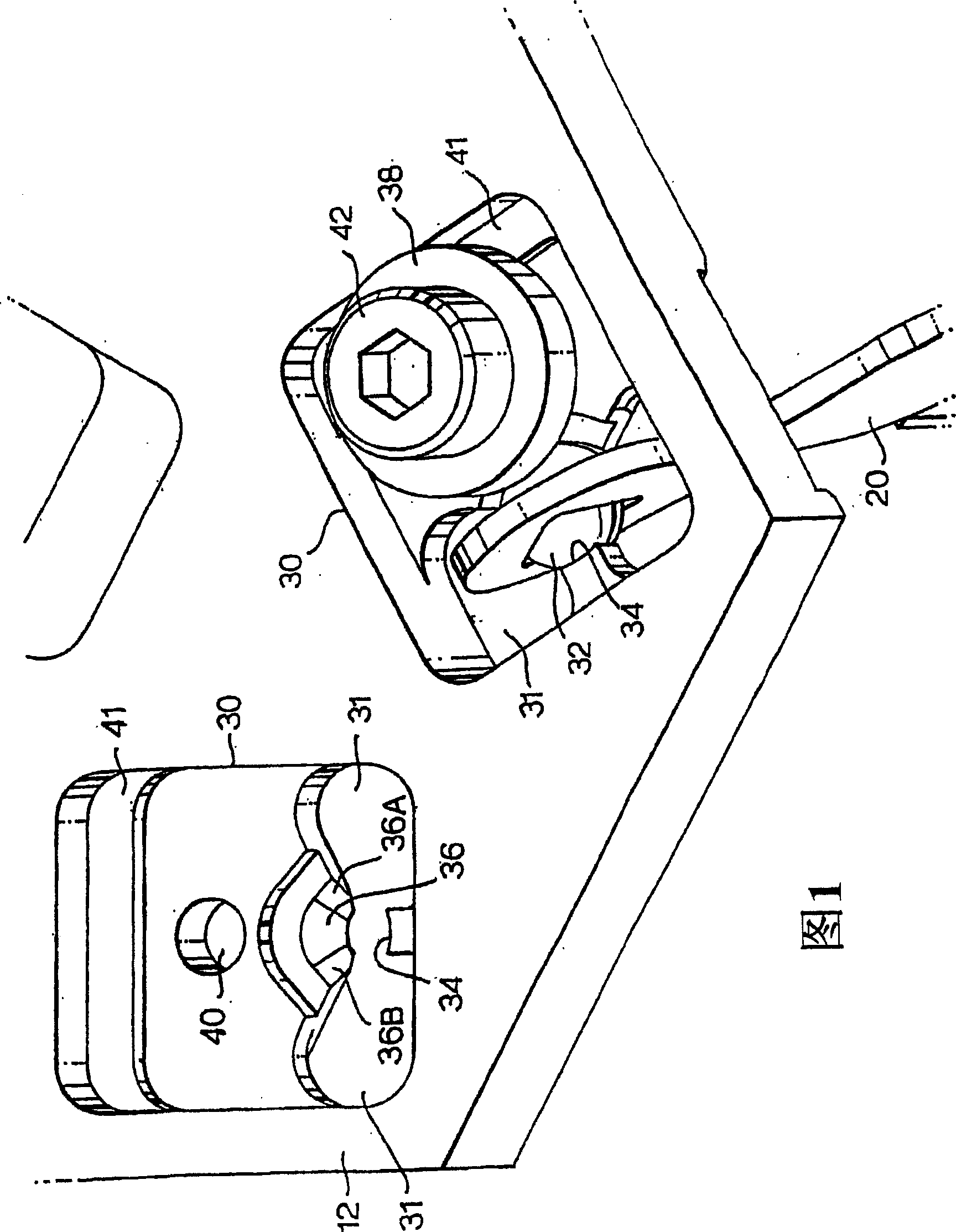
[0022] Figure 1 is an isometric view of two pivot joints. The first structure consists of a seat for a sphere and a sphere. One platform 12 has structured cutouts 30 (seats). The ball 32 of the pivot joint is supported in the cut-out 30 by the surface defined by the edge of the cut-out. In FIG. 1 two cutouts 30 are shown, one with the other parts of the ball joint in situ and one without the other parts of the ball joint.
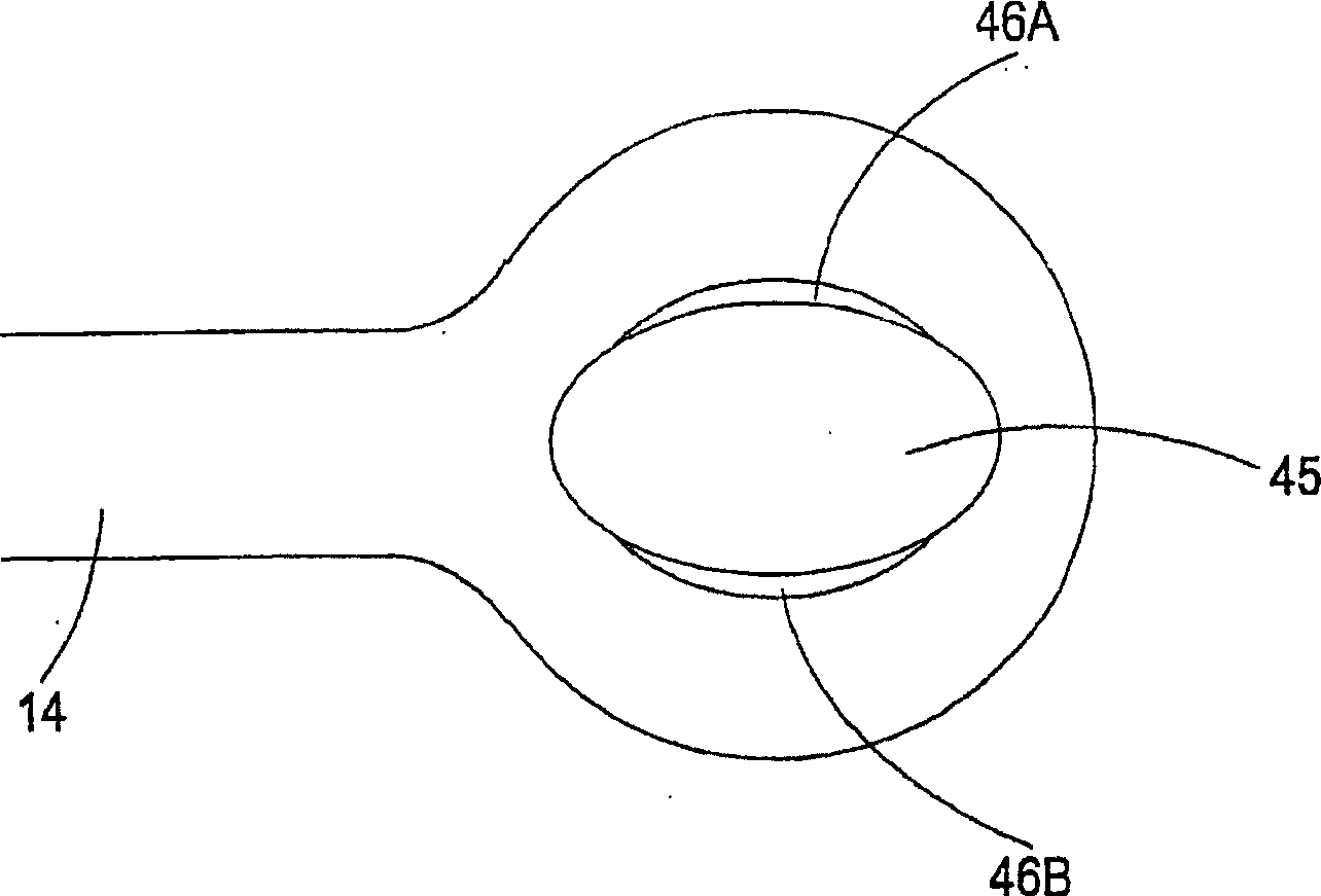
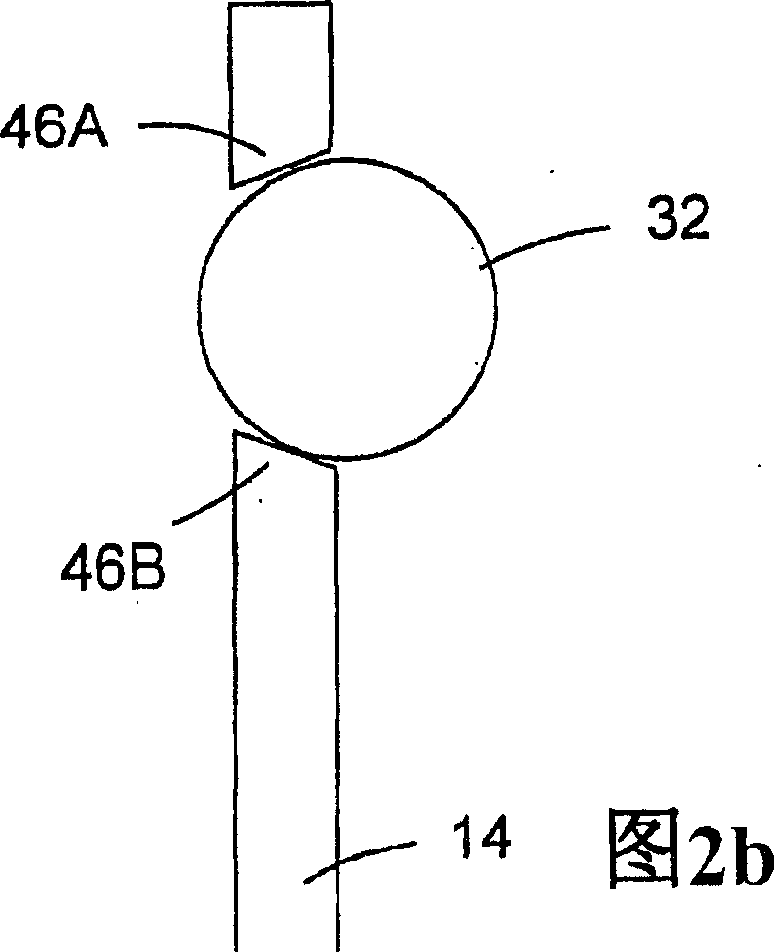
[0023] The ball 32 is supported by two opposing surfaces 34 , 36 of the cutout 30 . The first curved surface 34 is in contact with one side of the ball 32 and the second curved surface 36 is in contact with the lower surface of the ball 32 at two contact points 36A, 36B. The position of the ball 32 is determined by the three contact points 34 , 36A, 36B and a fourth contact point provided by a clamp 38 , 42 . The ball is thus kinematically reproducible in the above-mentioned cutout.
[0024] In this example, the clamp includes a washer 38 and a fixing ...
PUM
Abstract
The invention discloses a pivot joint comprising a first structure (10, 12), a second structure (14, 20, 102, 104), the first structure having a The sphere (32, 114), the second structure is movable relative to the first structure, and is in contact with the sphere through a bearing (43, 46, 126), which contact determines the position of the pivot point, wherein the bearing is shaped to receive ball, and the pivot point remains substantially in its defined position as the bearing wears. The second structure is biased (108, 110) into contact with the ball (32, 114). The bearing comprises two or three bearing surfaces (43A, 43B, 43C, 46A, 46B, 126A, 126B, 126C) which are inclined at an angle relative to the normal to the plane of the bearing surfaces. A third structure (104) may be provided that is movable relative to the first and second structures. The ball is held in the seat by two contact points with the seat, which are provided at diametrically opposite positions on the ball. The invention also discloses a positioning instrument comprising a pivot joint.
Description
technical field [0001] The present invention relates to a pivot joint, in particular a ball joint. Background technique [0002] Pivot joints comprising a ball on the rod are known. In such a pivot joint the ball is located in a socket from which the rod protrudes. These pivot joints suffer from a lack of precision, mainly due to the fact that their spherical parts are not exactly spherical. Another disadvantage is that parts cannot be replaced cheaply when worn. As such joints wear out, their positioning accuracy decreases, which can lead to undesired movements of the pivot point. [0003] Precision balls (ie ball bearings) can be manufactured very precisely by grinding. Contents of the invention [0004] The invention provides a pivot joint, comprising: [0005] a first structure comprising a sphere held in a seat; [0006] A second structure, movable relative to the first structure, in contact with the aforementioned sphere through bearings, this contact defining ...
Claims
Application Information
Patent Timeline
Application Date:The date an application was filed.
Publication Date:The date a patent or application was officially published.
First Publication Date:The earliest publication date of a patent with the same application number.
Issue Date:Publication date of the patent grant document.
PCT Entry Date:The Entry date of PCT National Phase.
Estimated Expiry Date:The statutory expiry date of a patent right according to the Patent Law, and it is the longest term of protection that the patent right can achieve without the termination of the patent right due to other reasons(Term extension factor has been taken into account ).
Invalid Date:Actual expiry date is based on effective date or publication date of legal transaction data of invalid patent.