Super-conducting cable

A superconducting cable and cable technology, applied in superconducting devices, superconducting/high-conducting conductors, circuits, etc., can solve problems such as heat intrusion

Inactive Publication Date: 2009-09-30
SUMITOMO ELECTRIC IND LTD
View PDF6 Cites 0 Cited by
  • Summary
  • Abstract
  • Description
  • Claims
  • Application Information

AI Technical Summary

Problems solved by technology

When the heat insulating element comes into contact with the inner and outer pipes in this way, the heat from the outside is easily conducted from the outer pipe to the inner pipe via the heat insulating element, causing a problem of increased intrusive heat

Method used


Image

  • Super-conducting cable
  • Super-conducting cable

Examples


Embodiment Construction

[0050]

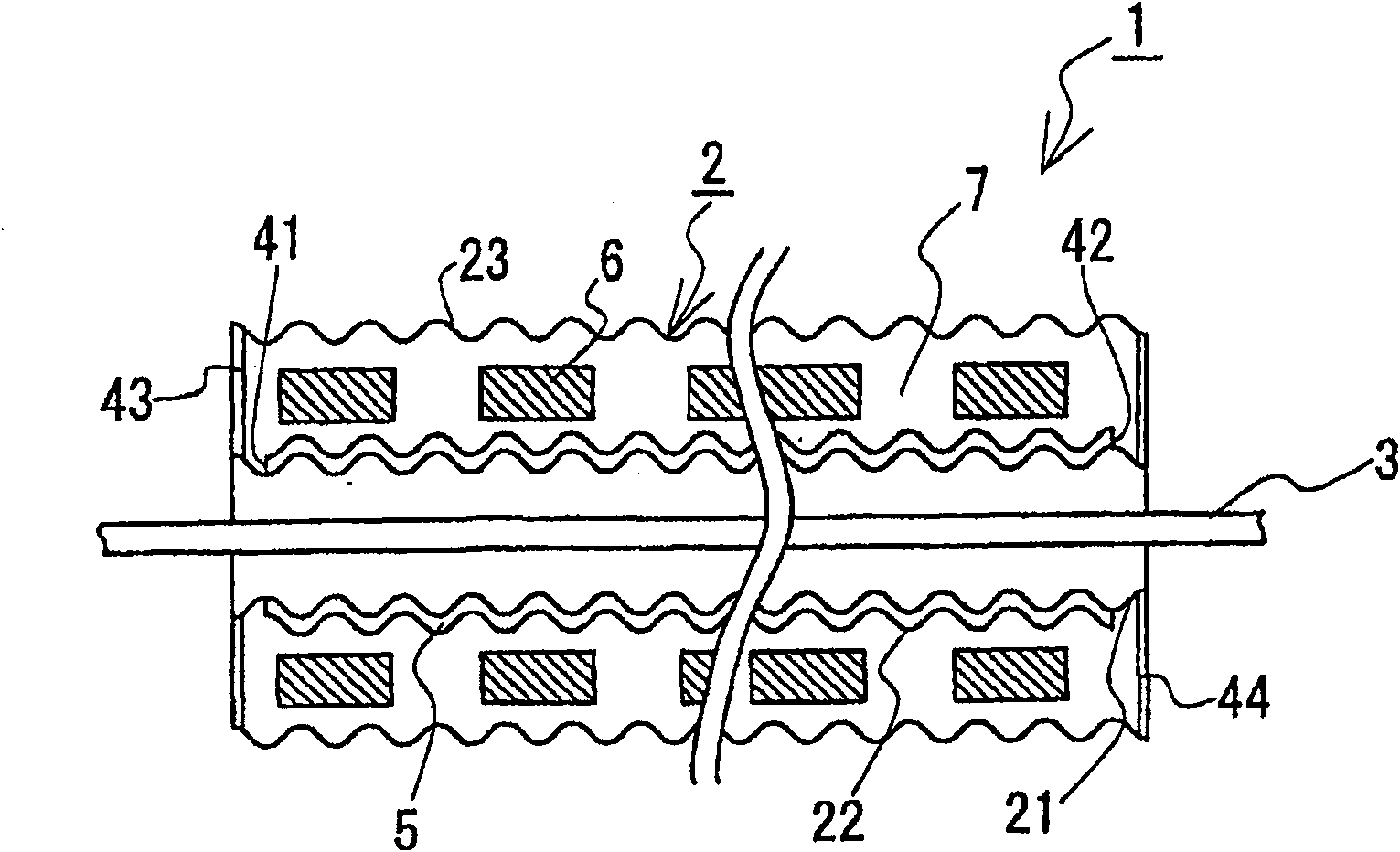
Embodiments of the superconducting cable according to the present invention will be described below. figure 1 is an outline sectional view of both ends of the superconducting cable according to the present invention.

[0051]

[overall structure]

The superconducting cable 1 used in the embodiment includes a single-core cable core 3 inside a heat insulating tube 2, and is used for a DC cable. figure 1 A sectional view of the outer shape of the superconducting cable 1 is shown, and the length of the thermal insulation tube 2 is made shorter than the length of the cable core 3 .

[0052]

[cable core]

Although not shown, the cable core 3 contained inside the heat insulating tube 2 continuously includes a forming member, a superconductor layer, an insulating layer, an outer conductor layer, and a protective layer from the center thereof.

[0053]

As the shaped part, a solid part twisted with a wire button or a hollow part using a metal tube can be used. As a s...


PUM


Abstract

Provided is a superconducting cable capable of improving a thermal insulation function by a thermal insulation tube and maintaining the thermal insulation function of the thermal insulation tube to a minimum even when the exterior of the thermal insulation tube is damaged during transportation. The thermal insulation pipe (2) containing the cable core (3) of the superconducting cable (1) includes a first metal pipe (21), a second metal pipe (22) and a third metal pipe ( twenty three). The inner heat insulation part (5) is formed between the first metal pipe (21) and the second metal pipe (22), and the outer heat insulation part (7) is formed on the inner side of the third metal pipe (23) and the inner heat insulation on the outside of part (5). The thermal insulation function of the thermal insulation portion on the outer side is set lower than that of the thermal insulation portion on the inner side thereof.

Description

technical field [0001] The present invention relates to a superconducting cable formed by accommodating a cable core in a heat insulating tube. Background technique [0002] Generally, a superconducting cable is formed by accommodating a single-core cable or a cable core twisted together by a plurality of members inside a heat insulating tube (for example, refer to Patent Reference 1). [0003] The cable core consists of a shaped part, a superconductor, an insulating layer, a shielding layer, and a protective layer successively from the central side. Such as figure 2 As shown, the heat insulating pipe A is composed of a bimetallic pipe of the inner pipe A1 and the outer pipe A2, and generally, both pipes use a corrugated pipe formed of a corrugated pipe shape along the longitudinal direction so as to be easily bent. In addition, a single core or a cable core twisted together by a plurality of members B buttons is included on the inner side of the inner tube A1. A re...

Claims


Application Information

Patent Timeline
Patent Type & Authority Patents(China)
IPC IPC(8): H01B12/14F16L9/06F16L9/18F16L59/14
CPCH01B12/14Y02E40/645F16L59/143F16L59/141F16L59/065Y02E40/60H01B12/00
Inventor 广濑正幸畑良辅
Owner SUMITOMO ELECTRIC IND LTD
Why Eureka
Try Eureka