Piston reciprocating magnetic repulsion generating (electric) module and its combined application system

A technology of electric and piston rings, applied in the direction of electric components, electrical components, electromechanical devices, etc.

Inactive Publication Date: 2007-07-18
孙华君
View PDF0 Cites 9 Cited by
  • Summary
  • Abstract
  • Description
  • Claims
  • Application Information

AI Technical Summary

Problems solved by technology

This leads to the complete waste of small external forces that often occur in many lives and in nature, which is not conducive to energy conservation.

Method used


Image

  • Piston reciprocating magnetic repulsion generating (electric) module and its combined application system
  • Piston reciprocating magnetic repulsion generating (electric) module and its combined application system
  • Piston reciprocating magnetic repulsion generating (electric) module and its combined application system

Examples


specific Embodiment approach

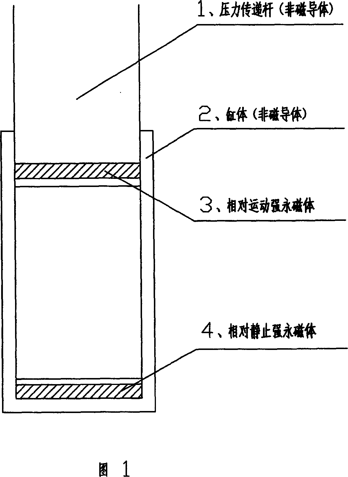
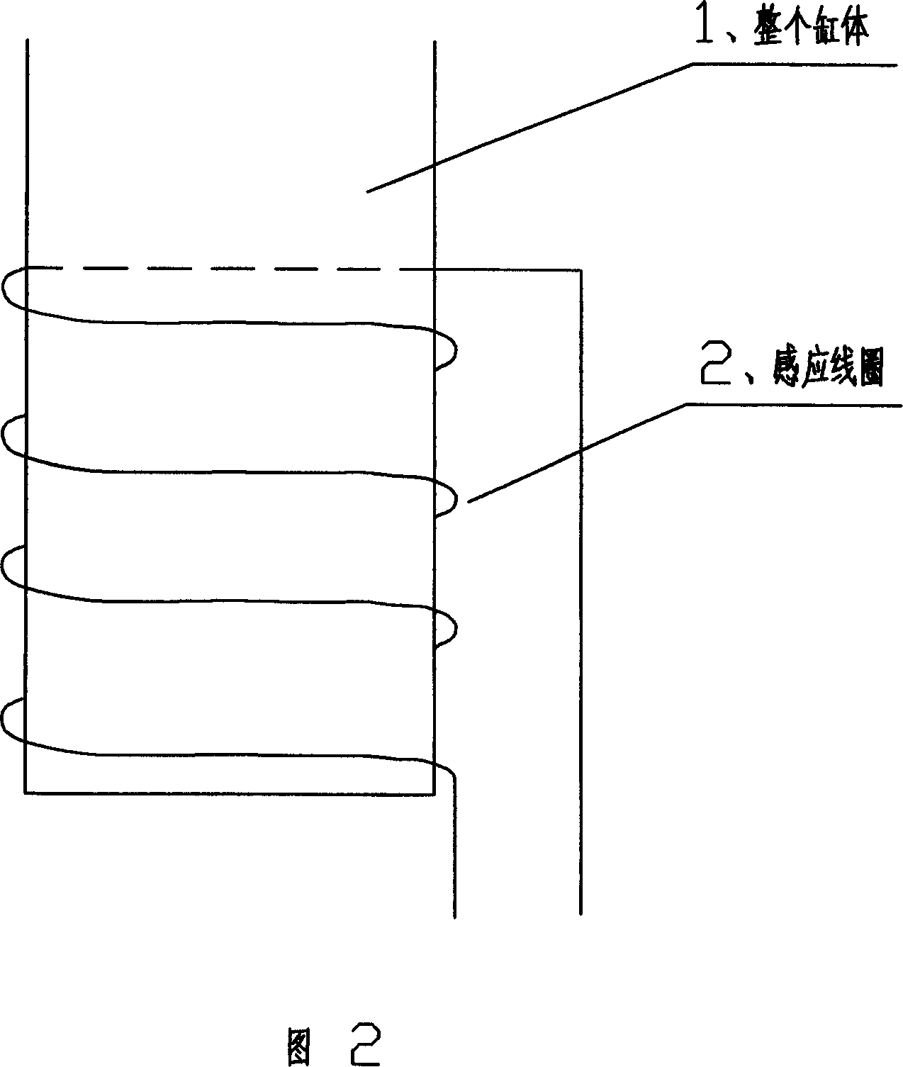
[0018] When the cylinder 1 moves back and forth under force, a current is generated in the coil 2.

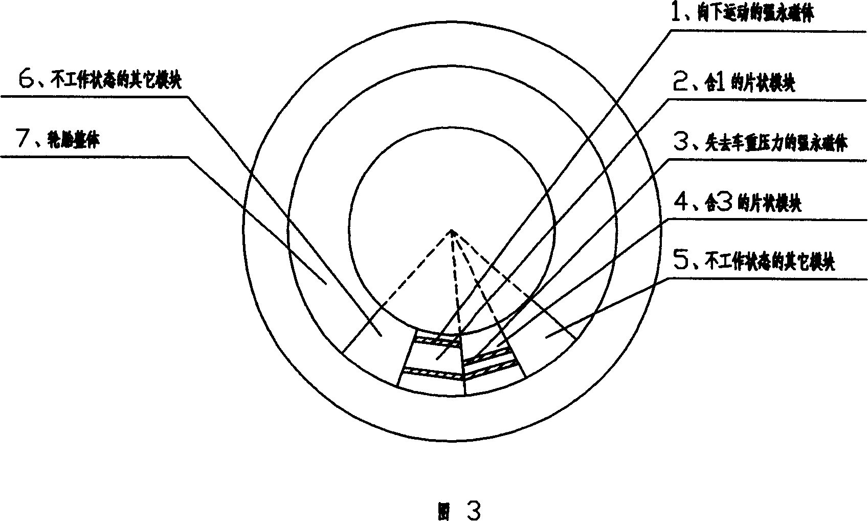
[0019] In Figure 3, 1 is the strong permanent magnet at the lower part of the pressure transmission rod that is moved downward by the pressure of the vehicle weight, 2 is the entire sheet module including 1, and 3 is the strong permanent magnet at the lower part of the pressure transmission rod that has just lost the pressure of the vehicle weight , 4 is the whole sheet module including 3, 5 is other modules in non-working state, 6 is other modules in non-working state, and 7 is the whole tire.

detailed description

[0020] When 7 tires rotate to the position shown in Figure 3, 1 receives the vehicle weight pressure downwards, and the coil outside the cylinder generates an induced current, and 3 loses the vehicle weight pressure, and the coil outside the cylinder generates an induced current, 2, 4, 5, 6, etc. Form a ring embedded system.

[0021] In Fig. 4, 1 is a strong per...


PUM


Abstract

This invention relates to a generating module based on a magnetic spring composed of a cylinder, a strong magnet (an electromagnet in electromotive system) fixed on the interlayer of the bottom of the cylinder, a piece of pressure transfer bar with suitable shape and with strong magnet at the bottom pressed to the bottom of the cylinder along the inside wall of the cylinder and an induction coil winded on the cylinder.

Description

Technical field [0001] The present invention relates to a generating or auxiliary generating (electrical) system. Background technique [0002] According to the principle of electromagnetic induction, modern power generation devices are mostly generator sets composed of rotors and stators that use external force to move in a circular motion, and use a large-scale industrial concentration method to increase power generation, so they are huge in size. This causes the small external force that often occurs in many lives and in nature to be completely wasted, which is not conducive to energy conservation. In fact, the magnetic induction current originates from the change of the magnetic flux of the closed coil, not only from the circular motion cutting the magnetic field line of the general generator. In the era of energy shortage, we should promote the gradual use of various small energy sources around us, improve energy utilization efficiency, and advocate the use of green en...

Claims


Application Information

Patent Timeline
Patent Type & Authority Applications(China)
IPC IPC(8): H02K35/02H02K33/16
CPCH02K35/02H02K7/1876
Inventor 孙华君
Owner 孙华君
Why Eureka
Try Eureka