

Gas hermetic apparatus and hermetic method of glass base plate annealing furnace
A glass substrate and annealing furnace technology, which is applied in the field of manufacturing ultra-thin glass substrates
- Summary
- Abstract
- Description
- Claims
- Application Information
AI Technical Summary
Problems solved by technology
Method used
Image

Examples
Embodiment 1
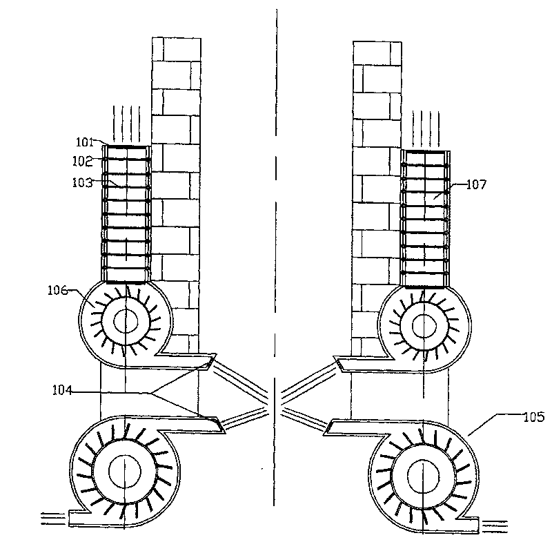
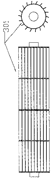
[0026] Such as figure 1 The air lock system at the lower end of the annealing furnace, the clean air is heated to the necessary temperature by heating the metal heat sink 103, the preheated clean air passes through the blower 106 to form a gas blocking layer at the lower end of the glass ribbon, and the grid-shaped regulating plate 104 is used to adjust The direction angle of the air curtain is to minimize the possibility of the air curtain returning to the upper side after it touches the glass ribbon. An air tractor 105 is added at a suitable position at the lower end, which is used to form a negative pressure at the lower end of the air curtain, thereby pulling The return air of the air curtain flows downward.
[0027] Similarly, the inlet of the air traction machine 105 (traction fan) adopts the structure of grid-shaped regulating plate 104, which is used to adjust the wind direction for its formation of traction. The air volume produced by the air tractor 105 (traction fa...
Embodiment 2
[0029] Such as figure 1 The air lock system at the lower end of the annealing furnace, the clean air is heated to the necessary temperature by heating the metal heat sink 103, the preheated clean air passes through the blower 106 to form a gas blocking layer at the lower end of the glass ribbon, and the grid-shaped regulating plate 104 is used to adjust The direction angle of the air curtain is to minimize the possibility of the air curtain returning to the upper side after it touches the glass ribbon, and an air tractor 105 is added at a suitable position at the lower end, which is used to form a negative pressure at the lower end of the air curtain, thereby pulling The return air of the air curtain flows downward.
[0030] Adjust the grid-shaped wind direction plate 104 at the outlet of the blower 106 so that the return air flows as far as possible below the annealing furnace. Gradually increase the deflection direction of the grid-shaped wind direction plate 104, and when ...
Embodiment 3
[0032] Such as figure 1The air lock system at the lower end of the annealing furnace, the clean air is heated to the necessary temperature by heating the metal heat sink 103, the preheated clean air passes through the blower 106 to form a gas blocking layer at the lower end of the glass ribbon, and the grid-shaped regulating plate 104 is used to adjust The direction angle of the air curtain is to minimize the possibility of the air curtain returning to the upper side after it touches the glass ribbon, and an air tractor 105 is added at a suitable position at the lower end, which is used to form a negative pressure at the lower end of the air curtain, thereby pulling The return air of the air curtain flows downward.
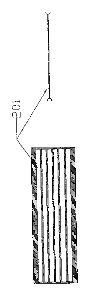
[0033] Figure 5 In order not to adopt the air traction machine 105, the effect diagram is formed by the air curtain without the deflection angle of the air blower 106 at the same time. It can be found that the return air after the air curtain reaches the glass ...
PUM
 Abstract
Description
Claims
Application Information