Motor

A technology of electric motor and hysteresis, applied in the field of electric motor, can solve the problems of low operation efficiency of electric motor

Inactive Publication Date: 2010-05-26
LG ELECTRONICS INC
View PDF3 Cites 0 Cited by
  • Summary
  • Abstract
  • Description
  • Claims
  • Application Information

AI Technical Summary

Problems solved by technology

Due to this, the motor runs inefficiently

Method used


Image

  • Motor
  • Motor
  • Motor

Examples


Embodiment Construction

[0019] Reference will now be made in detail to the preferred embodiments of the invention, examples of which are illustrated in the accompanying drawings.

[0020] Hereinafter, a motor according to an embodiment of the present invention will be described in detail with reference to the accompanying drawings.

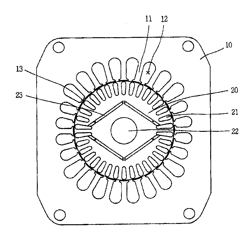
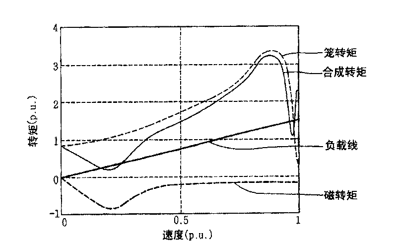
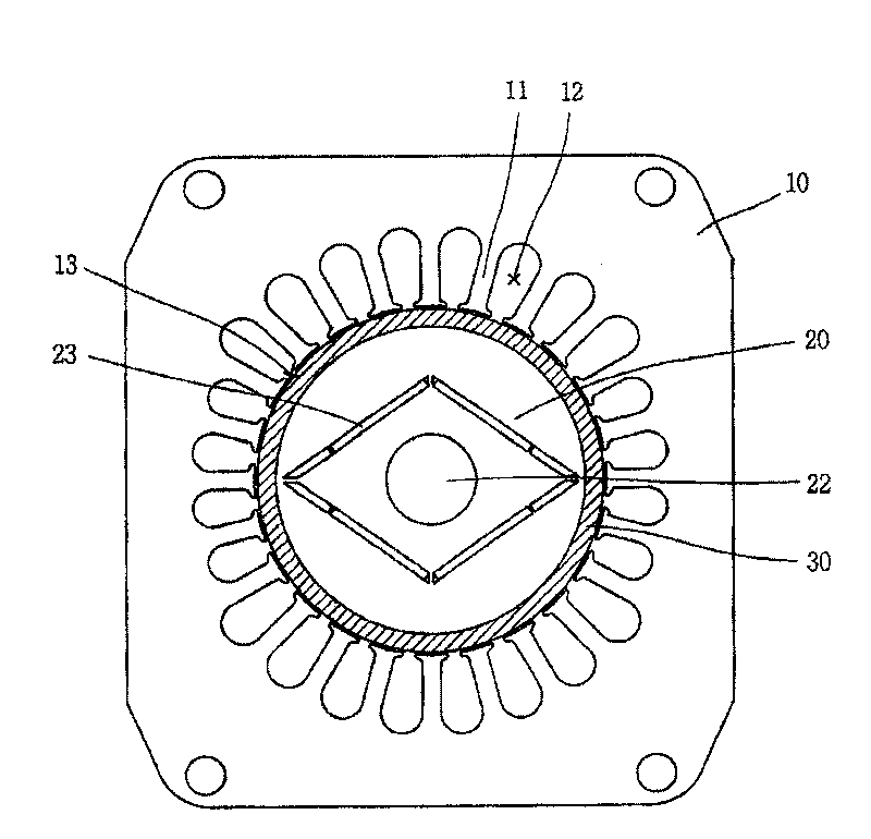
[0021] image 3 is a schematic diagram of a motor according to an embodiment of the present invention. Figure 4 show image 3 The torque characteristic of the electric motor shown in the relationship curve with the speed change. In this example, with figure 1 and figure 2 The same components are denoted by the same reference numerals and will not be described in detail.

[0022] Such as image 3 and Figure 4 As shown, the motor according to the embodiment of the present invention includes: a stator 10 having a plurality of teeth 11 forming a plurality of slots 12, a through hole 13 formed at the center by the ends of the plurality of teeth 11, and a surrounding...


PUM


Abstract

A motor is disclosed. A motor according to the present invention includes: a stator including a plurality of teeth that forms a plurality of slots, a through hole formed in the center by the tips of the plurality of teeth, and a coil that is wound around the teeth and generates rotating magnetic field by applying electricity; a rotator that is rotatably inserted in the through hole and has an axlehole into which a rotating axle is inserted and a plurality of permanent magnets disposed around the axle hole; and a hysteresis band that is disposed on an outer periphery of the rotator. Accordingto the present invention, since the hysteresis band is disposed on the outer periphery of the rotator, the motor can overcome the braking torque by the permanent magnets in transition state and startsnormally and generates magnetic flux in normal operation with synchronous speed, thus increasing the efficiency of the motor.

Description

technical field [0001] The present invention relates to an electric motor, and more particularly to a high-efficiency electric motor capable of overcoming the braking torque produced by permanent magnets in a transient state and normally starting, and capable of producing magnetic flux. Background technique [0002] figure 1 is a schematic diagram of an electric motor according to the prior art, figure 2 A graph showing the relationship between the torque characteristic of the motor and the speed change is shown. [0003] refer to figure 1 , the motor according to this prior art includes: a plurality of teeth 11 forming a plurality of slots 12; a through hole 13 formed at the center by means of the ends of the plurality of teeth 11; a stator 10 having a surrounding A coil (not shown) wound around the tooth 11, which generates a rotating magnetic field when energized; a shaft hole 22, which is rotatably embedded in the through hole 13, and a rotating shaft (not shown in ...

Claims


Application Information

Patent Timeline
Patent Type & Authority Patents(China)
IPC IPC(8): H02K21/12H02K1/27H02K1/16H02K3/12
CPCH02K19/106H02K1/276H02K1/27
Inventor 沈长昊李成浩金在民崔在学朴镇洙
Owner LG ELECTRONICS INC
Why Eureka
Try Eureka