Fluidized-bed coating machine

A technology of coating machine and fluidized bed, applied in the direction of chemical instruments and methods, chemical/physical processes, and methods of granulating raw materials, etc., can solve problems such as waste, affecting the disintegration and dissolution of active ingredients, and achieve convenience and ease. Release, firm adhesion, and improve the effect of true sphericity

Inactive Publication Date: 2007-10-31
邹龙贵
View PDF2 Cites 14 Cited by
  • Summary
  • Abstract
  • Description
  • Claims
  • Application Information

AI Technical Summary

Problems solved by technology

This kind of direct spray drying for powder coating has some shortcomings: such as the packaging material penetrates into the material, causing waste, and affecting the disintegration and dissolution of active ingredients
The above-mentioned fluidized bed coating machine is only suitable for the coating of granular materials.

Method used


Image

  • Fluidized-bed coating machine
  • Fluidized-bed coating machine
  • Fluidized-bed coating machine

Examples


Embodiment 1

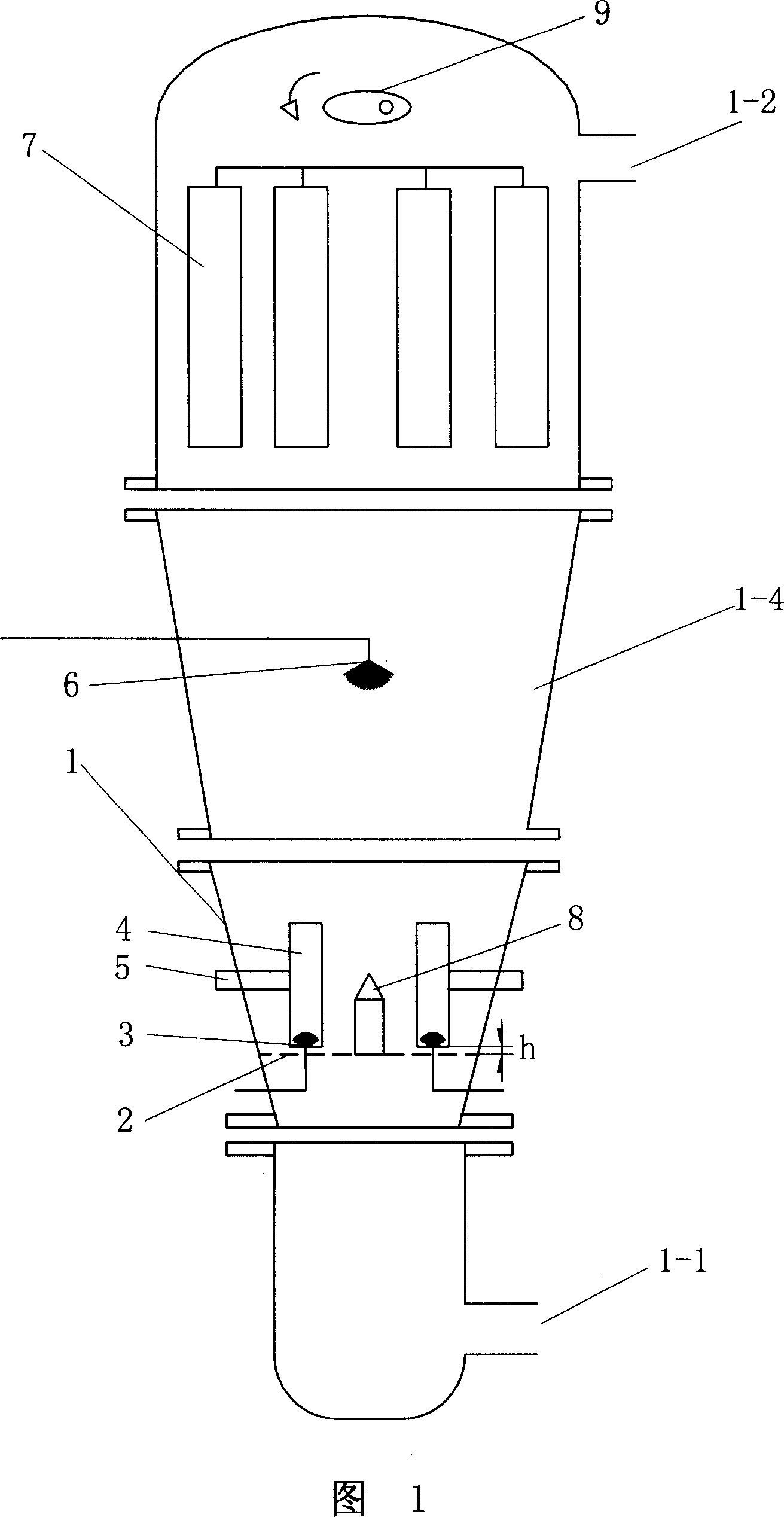
[0023] See Figure 1 and Figure 2. In this example, granulation and coating are completed in the same tank, which is especially suitable for the processing of slow-release and controlled-release pharmaceutical products. It includes a tank body 1, the tank body 1 has a dry air inlet 1-1 and an air outlet 1-2, the tank body 1 is provided with an air flow distribution plate 2, and the fluidization chamber 1-4 of the tank body 1 is in the shape of an inverted cone Form the expansion chamber. A cloth bag filter 7 is provided on the upper part of the tank body 1, and an eccentric rapping device 9 is provided above the filter 7. Filters and eccentric rapping devices are commercially available.

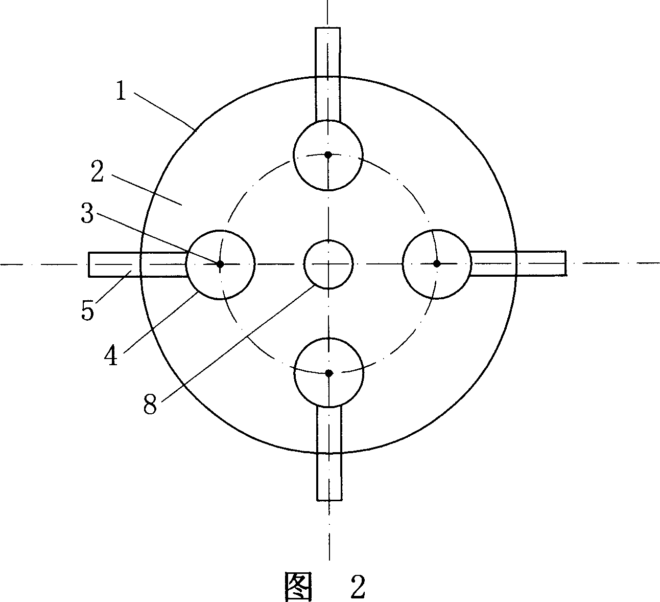
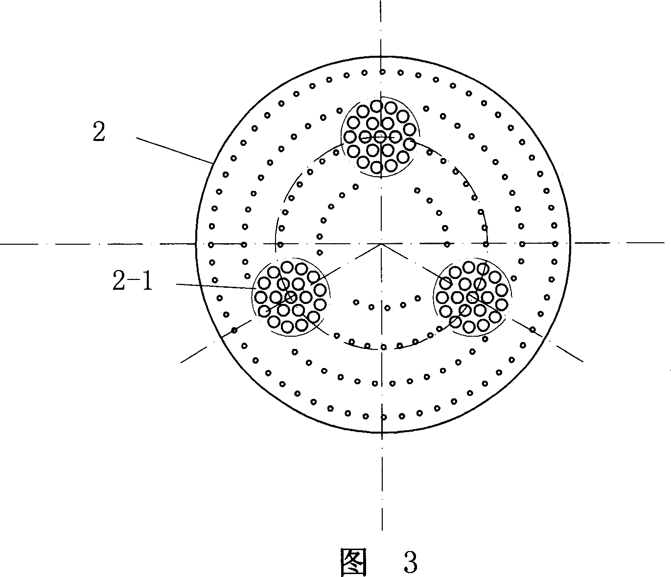
[0024] Referring to FIG. 3 , at least two large-hole areas 2-1 are provided on the airflow distribution plate 2, and generally 3-6 large-hole areas 2-1 can be optionally provided. The large hole areas 2-1 are evenly distributed on the same circumference, that is, the distances between the ce...

Embodiment 2

[0027] As shown in FIG. 3 , the air distribution plate 2 of this embodiment is provided with 3 large hole areas, and correspondingly, 3 guide cylinders are provided. All the other are identical with embodiment 1.

[0028] The embodiment in which 5 or 6 large hole regions are provided on the air distribution plate 2 can be made on the basis of the above description for those of ordinary skill in the art.

Embodiment 3

[0030] See Fig. 5, present embodiment is only coating machine. It includes a tank body 1, the tank body 1 has a dry air inlet 1-1 and an air outlet 1-2, the tank body 1 is provided with an air flow distribution plate 2, and the fluidization chamber 1-4 of the tank body 1 is in the shape of an inverted cone extension room. The upper part in the tank body 1 is provided with a screen filter 7 . The large hole area 2-1 on the airflow distribution plate 2 is set as required, as long as the opening ratio of the large hole area 2-1 is at least 65%. Above the air distribution plate 2 and facing each large hole area 2-1, there is a guide cylinder 4, and there is a gap h between the bottom surface of the guide cylinder and the air distribution plate, and the gap h is 3-15 mm. The center of the air distribution plate 2 is provided with a protrusion 8 whose head is a cone. A coating nozzle 3 is arranged corresponding to each guide cylinder 4, and the coating nozzle 3 protrudes from the...


PUM

PropertyMeasurementUnit
porosityaaaaaaaaaa
porosityaaaaaaaaaa

Abstract

The invention discloses a fluid bed tablet-coating machine, which is characterized by the following: possessing dry air inlet and tank of ventilating port; arranging air flow distribution plate and filter in the tank; arranging at least two big hole area on the same angular of even dispersing on the air flow dispersing plate; setting the perforated ratio of the big hole area at 65%; arranging guide barrel on the upper of the air flow dispersing plate; heading on each big hole area; possessing gap between the floor of the guide barrel and the air flow dispersing plate; arranging a dressing injector; corresponding to each guide barrel; projecting the dressing injector from the central hole of the big hole area of the air flow dispersing plate. This invention possesses high output, which can be fit for big scale industrial production.

Description

technical field [0001] The invention relates to a fluidized bed coating machine. Background technique [0002] Chinese Patent No. 00219230.6 discloses a granulation and coating machine in the utility model patent specification. Its cylinder is equipped with a trapping chamber, a drying chamber, and a fluidized bed. It is installed in the center of the fluidized porous plate with the opening facing upwards. There is a guide cylinder above the nozzle. There is a gap between the guide cylinder and the fluidized porous plate. The hole diameter is slightly larger. The utility model can realize the coating of particles, small particles and even large particles of various raw materials. Since the above utility model patent is a bottom spray coating machine, the direction of the coating mist sprayed by the spray gun is the same as the fluidization direction of the material, so the contact between the mist and the material is uniform and the continuity is good, and the aperture on ...

Claims


Application Information

Patent Timeline
Patent Type & Authority Applications(China)
IPC IPC(8): A61J3/06B01J2/00
Inventor 邹龙贵
Owner 邹龙贵
Why Eureka
Try Eureka