
Uterine sound

A technology of uterus and uterus, which is applied in medical science, diagnosis, catheterization, etc.

Inactive Publication Date: 2008-02-13
CYTYC CORP
View PDF0 Cites 2 Cited by
  • Summary
  • Abstract
  • Description
  • Claims
  • Application Information

AI Technical Summary

Problems solved by technology

Open position prevents end cap from perforating into uterine wall

Method used


Image

  • Uterine sound
  • Uterine sound
  • Uterine sound

Examples


Embodiment Construction

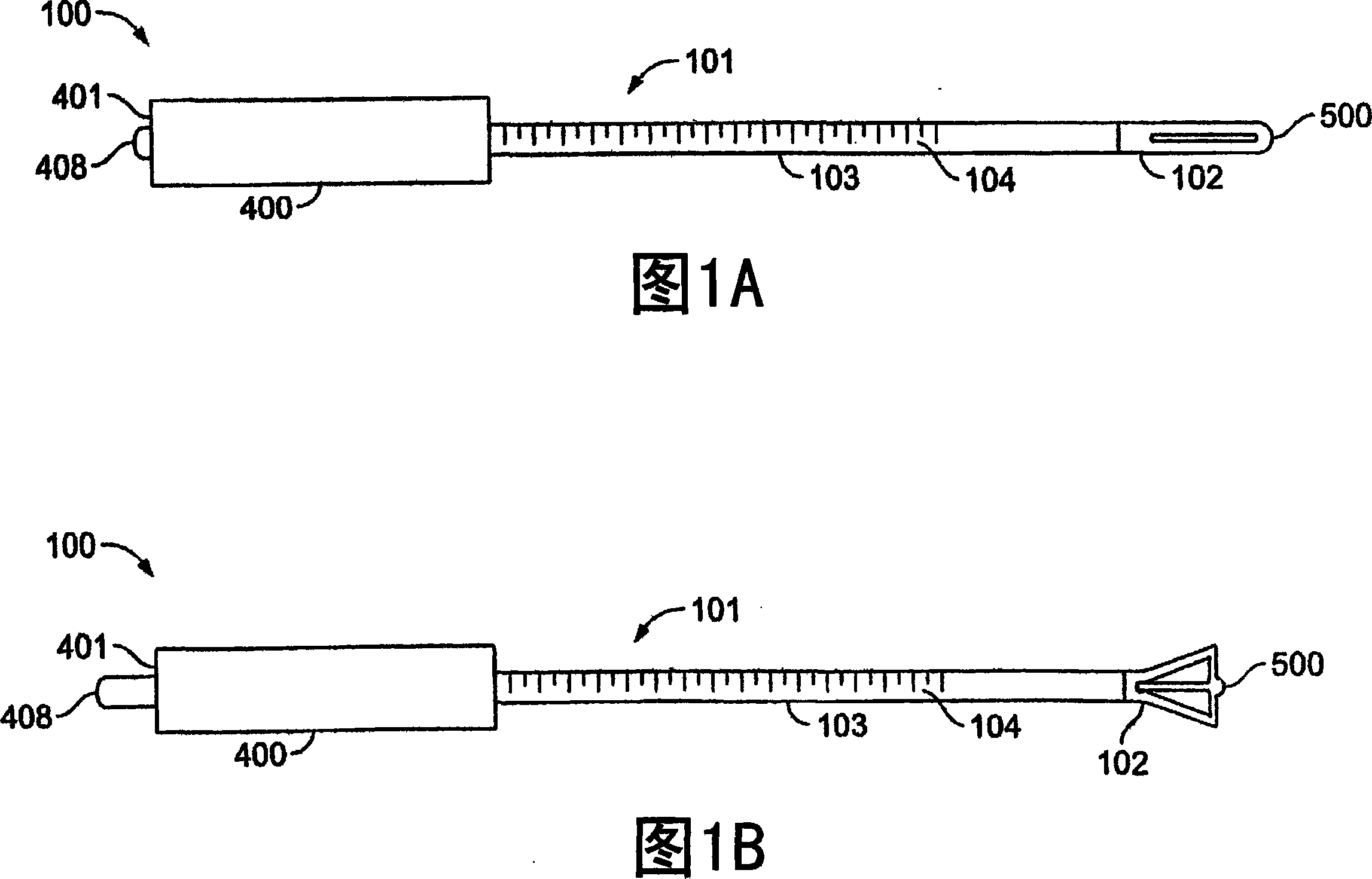
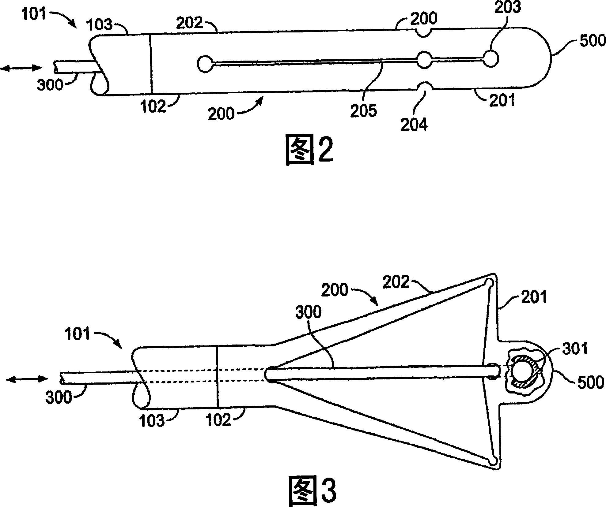
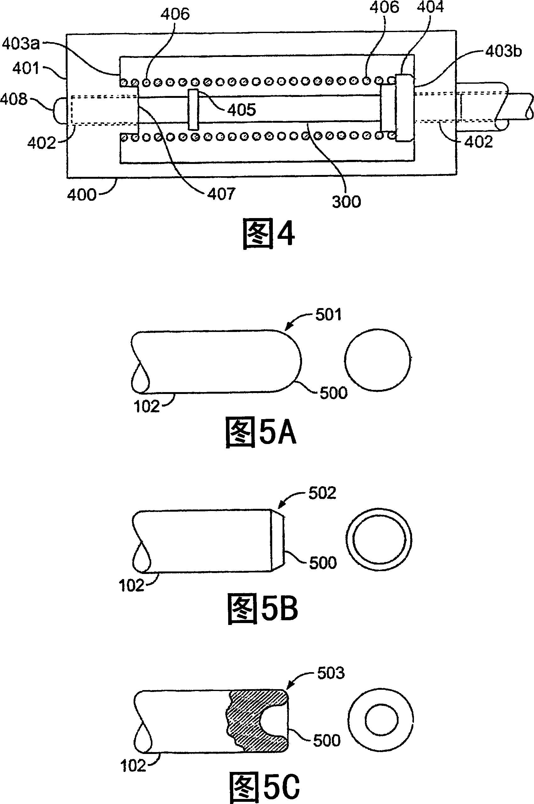
[0031] The uterine sound is configured to have an open and a closed position. Under normal operating conditions, the uterine sound is in the closed position for insertion into the uterus to measure uterine length. In situations where there is a risk that the uterine sound will perforate the uterine wall, the uterine sound is switched to the open position. The open position provides an expanded surface area for the distal end of the uterine sound to contact the uterine wall and resists the uterine sound from perforating the uterine wall.

[0032] Referring to Figures 1A and 1B, one embodiment of a uterine sound 100 is shown. In FIG. 1A , uterine sound 100 is in a closed position and configured for insertion into the uterus. In Figure IB the uterine sound 100 is in the open position; the geometry of the end cap 102 has changed from having a relatively small distal end to having an enlarged surface area.

[0033] In the illustrated embodiment, the uterine sound 100 includes an e...


PUM

PropertyMeasurementUnit
Lengthaaaaaaaaaa
Lengthaaaaaaaaaa
Lengthaaaaaaaaaa

Abstract

A uterine sound is configured having an open and a closed position. Under normal operating conditions, the uterine sound is in the closed position for insertion into a uterus to measure the length of the uterus. Under conditions where there is a risk of the uterine sound perforating a uterine wall, the uterine sound switches into an open position. The open position provides an enlarged surface area of a distal end of the uterine sound that is in contact with a uterine wall and resists perforation by the uterine sound of the uterine wall.

Description

technical field [0001] The present invention relates to medical devices. Background technique [0002] The human uterine cavity is roughly triangular and relatively flat, much like an envelope. The lumen is accessible via the cervical canal. The proximal end of the cervical canal, the external os, opens into the vagina, while the distal end, the internal os, opens into the uterine cavity. The apex of the triangular-shaped uterine cavity is at the internal cervical os, while the base is defined by the opening to the fallopian tubes (ie, the ostia). Uterine probing, ie determining the length of the uterus, is usually a covert procedure. The physician inserts a uterine sound through the cervix and advances the sound until it reaches the top or bottom of the uterine cavity, the base of the triangle between the ostia of the fallopian tubes. The length from the inner fundus to the outer cervical os can be measured directly using the scale printed on the probe shaft. Physician...

Claims


Application Information

Patent Timeline
IPC IPC(8): A61B5/107
CPCA61B5/1076A61B5/103A61B5/107
Inventor R·M·桑普森E·H·伊拉里奥B·J·伯利
Owner CYTYC CORP
Learn More