Mechanical pin

A technology of machinery and refills, applied in mechanical pencils, printing, writing utensils, etc., can solve problems such as deviation

Active Publication Date: 2008-05-07
A W FABER CASTELL GMBH & CO
View PDF3 Cites 0 Cited by
  • Summary
  • Abstract
  • Description
  • Claims
  • Application Information

AI Technical Summary

Problems solved by technology

plus process-dependent tolerances
Finally, deviations from the nominal dimensions also occur during the manufacture of the refill tip or the sliding area, so that, depending on the tolerances, high or low frictional forces of the refill actuator in the sliding area also result
The refill brake, possibly with the return of the refill tubing connected to it, can therefore require different forces depending on the tolerances of the individual pens, which is not satisfactory

Method used


Image

  • Mechanical pin
  • Mechanical pin
  • Mechanical pin

Examples


Embodiment Construction

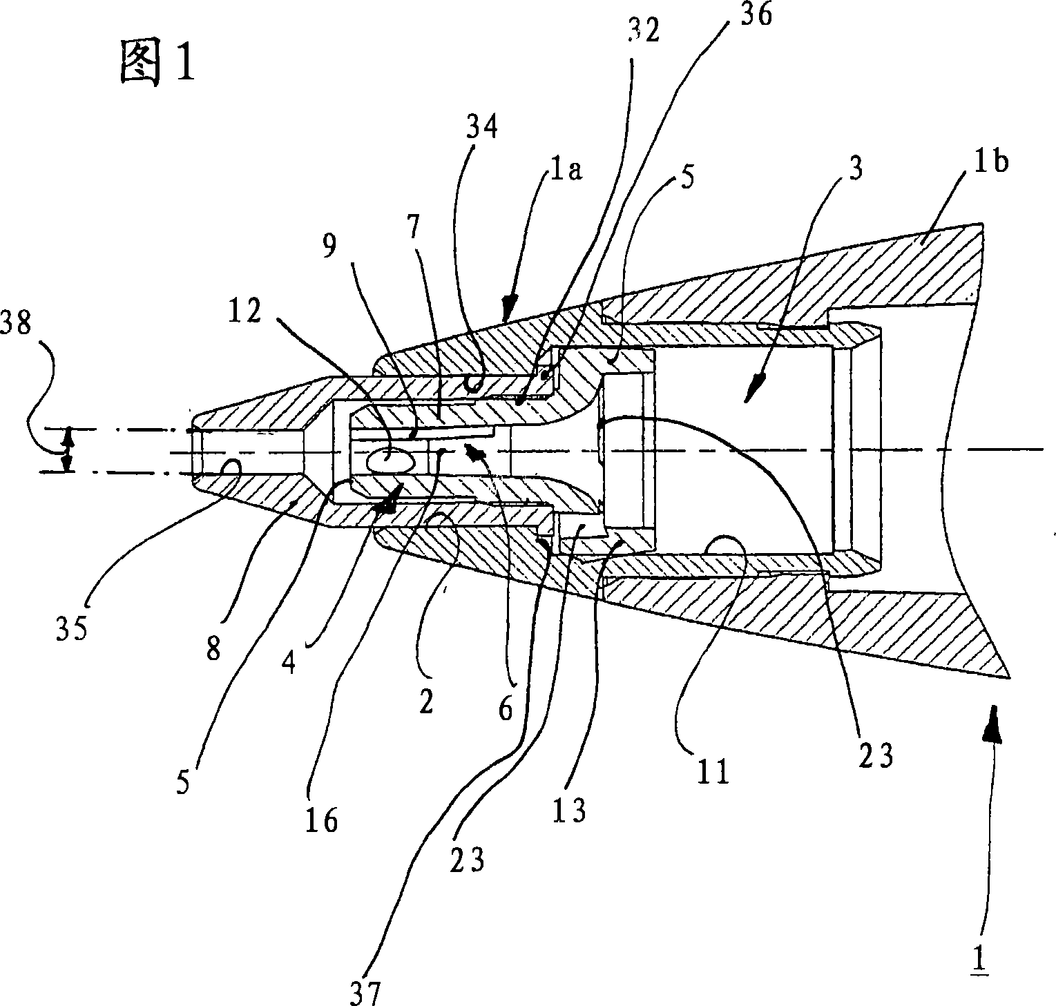
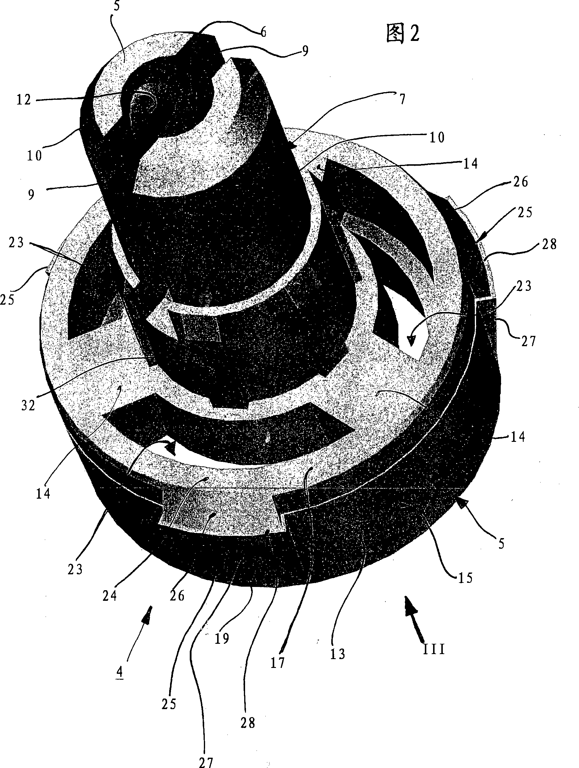
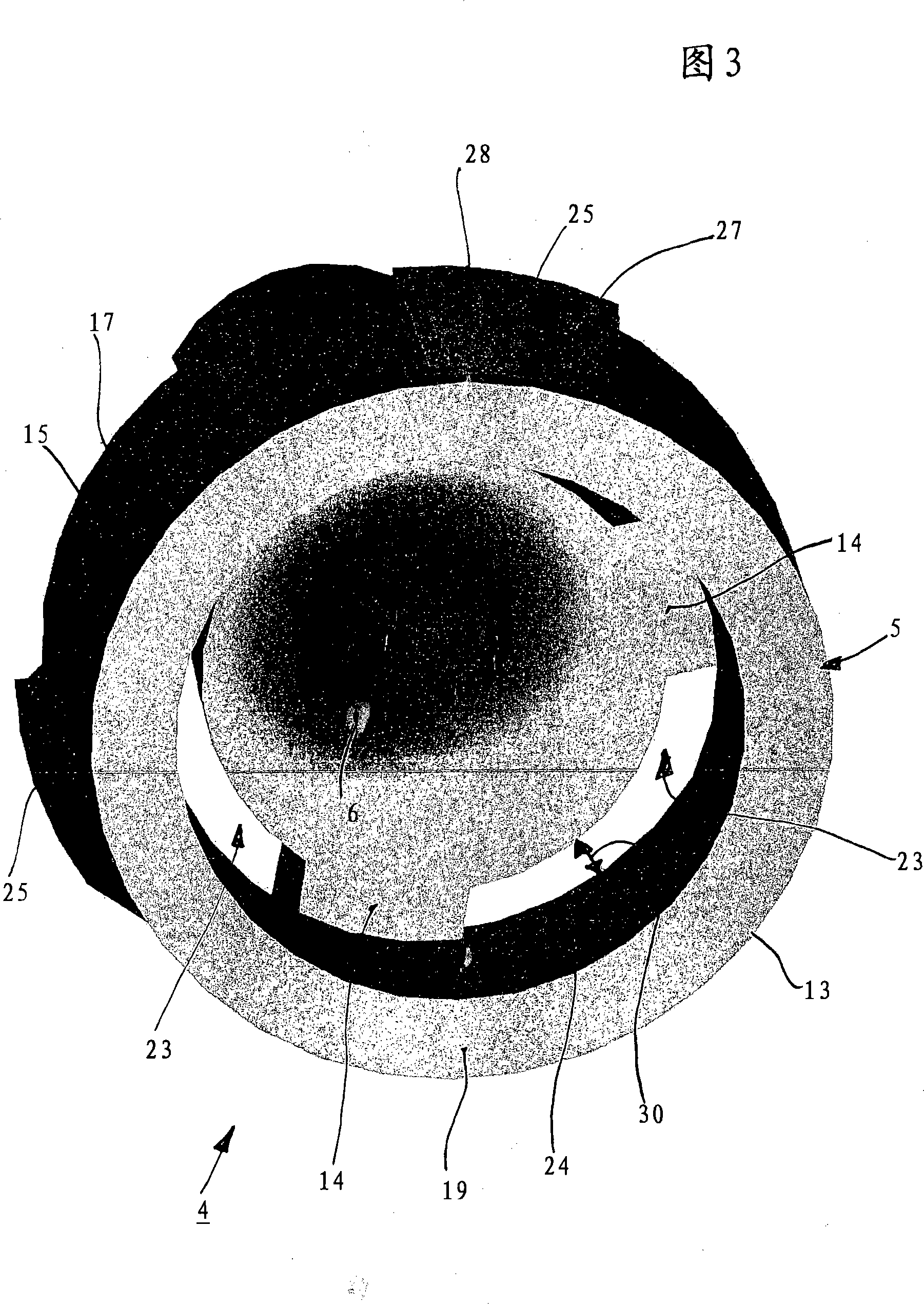
[0020] As can be seen in FIG. 1, a pen 1 of the present invention includes a shaft 1b having a tip 1a at its front end. A sliding region 3 is present in the tip 1a. Arranged axially displaceably therein is a lead stopper 4 designed as a one-piece plastic injection-molded part. The lead stopper 4 comprises a substantially cylindrical clamping body 7 through which a hole 6 extending concentrically to its central longitudinal axis or the central longitudinal axis 16 of the lead stopper passes and on which the lead capillary tube is fitted. 8. Starting from the front face 5 of the clamping body 7, two diametrically opposite axial grooves 9 are formed therein. In this way, two diametrically opposite clamping tongues 10 are formed, which are each provided with a radially inwardly protruding projection 12 on their inner faces. If the refill is fed through the hole 6 by means of the advancing mechanism of the pen 1, it passes through the protrusion 12, thus radially expanding the c...


PUM


Abstract

The pencil has a lead brake (4) with a cylindrical clamping body (7) for receiving and clamping a lead and axially penetrated from a bore hole (6). A sliding body is provided for axial guidance of the lead brake into a sliding area (3) of the pencil. The sliding body is designed as a sliding ring (13), which encompasses the clamping body (7) with a radial distance, and is connected with the clamping body via a plurality of radical battens (14) with opening (23) between one another, wherein the external surface of each wall sector segements which extend respectively between the two adjacent battens is respectively arranged with a projection (25) which extends along the radical direction.

Description

technical field [0001] The invention relates to a mechanical pen, in particular to a mechanical pencil. Background technique [0002] A kind of such such as by DE 19502779 known pen has a substantially sleeve-shaped bar that is provided with a tip, in which a refill reservoir and an axially propelled for a refill, such as by DE 3915331 C2 or the propulsion mechanism known from US 4 896 982. The lead advance includes a clamping device which can be manipulated by an axially effective pressure or rotation mechanism. The tip is passed by a guide channel which is connected to the lumen of the rod and serves to accommodate and guide the lead as it is moved outwardly from the tip by the advancing mechanism. Arranged in the rod is a part that clamps the cartridge in a frictional fit, a so-called cartridge stopper. The lead stopper comprises a cylindrical clamping body for frictionally clamping the lead stopper, which passes axially through a hole, and a slide body for axially gui...

Claims


Application Information

Patent Timeline
Patent Type & Authority Applications(China)
IPC IPC(8): B43K21/22
Inventor J·拉普斯D·鲍姆
Owner A W FABER CASTELL GMBH & CO
Why Eureka
Try Eureka