Direct current compressor drive circuit

A technology of DC compressor and drive circuit, applied in the direction of DC motor speed/torque control, AC motor control, electrical components, etc., can solve the problems of high hardware cost and high product competition pressure, so as to reduce hardware cost and ensure control Quality and the effect of improving market competitiveness

Inactive Publication Date: 2008-07-23
HISENSE (SHANDONG) AIR CONDITIONING CO LTD
View PDF0 Cites 7 Cited by
  • Summary
  • Abstract
  • Description
  • Claims
  • Application Information

AI Technical Summary

Problems solved by technology

[0003] In order to solve the problem that the existing DC compressor driving circuit must use an MCU chip with at least 6 PWM output ports to realize the driving control, the hardware cost is high and the product competition pressure is high, and a new DC compressor is provided. The motor drive circuit adopts the port expansion design to reduce the requirements on the port resources of the MCU chip, so that the 120-degree drive control of the DC compressor can be realized only by using the MCU chip with at least 2 PWM output ports, which greatly reduces the Reduced hardware costs and enhanced the market competitiveness of products

Method used


Image

  • Direct current compressor drive circuit
  • Direct current compressor drive circuit
  • Direct current compressor drive circuit

Examples


Embodiment 1

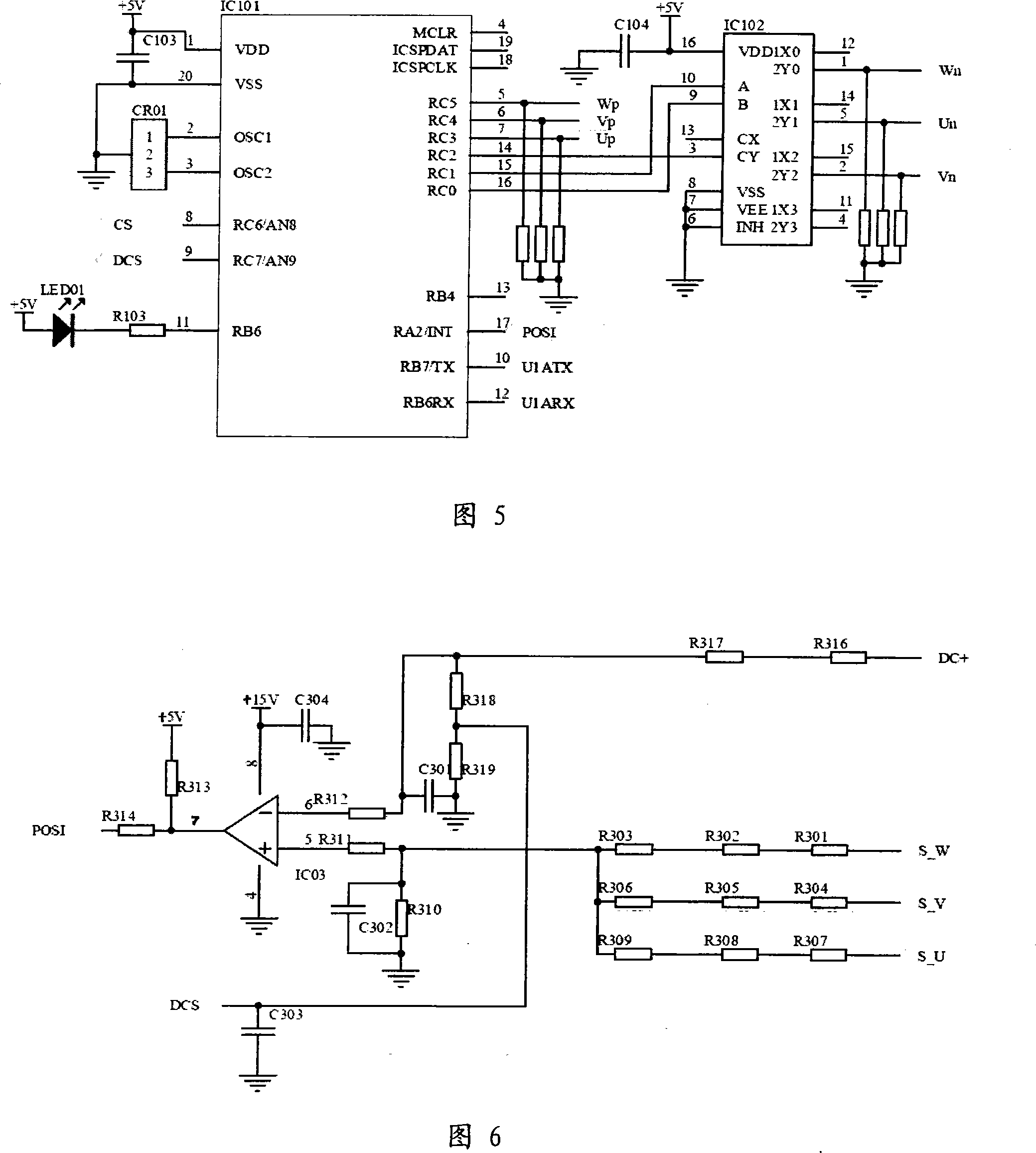
[0034] Embodiment 1, referring to FIG. 5 , this embodiment takes the MCU chip IC101 with 4 PWM output ports as an example to specifically illustrate its connection structure with the inverter circuit IPM.

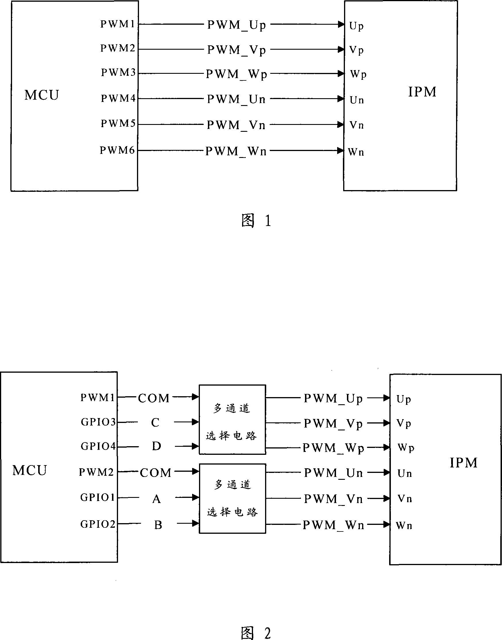
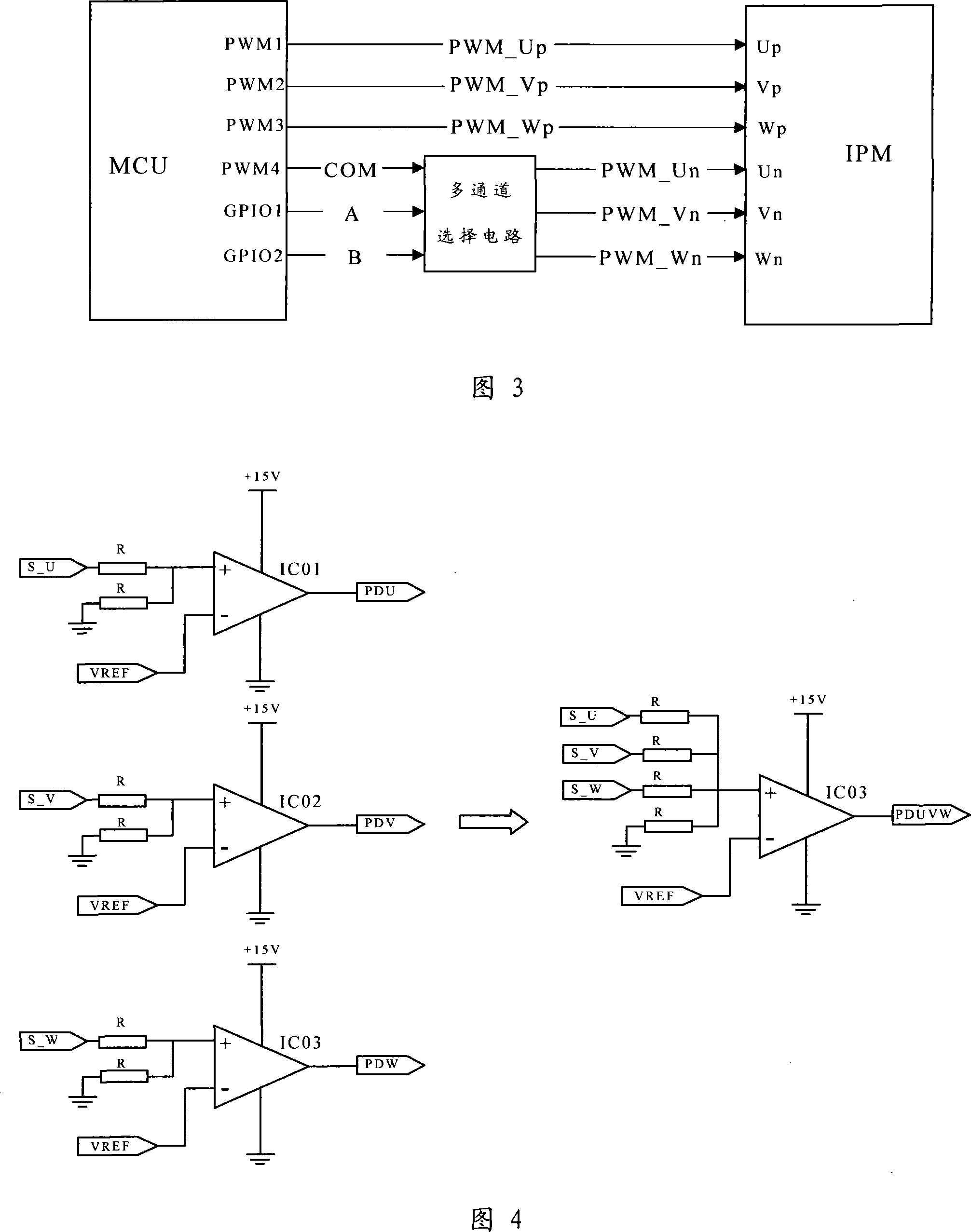
[0035] The MCU chip IC101 itself has four PWM output ports, namely RC5, RC4, RC3, and RC2. The four PWM outputs cannot meet the control requirements of a three-phase DC motor. Therefore, one of the PWM output ports needs to be expanded to provide Realize 6-way PWM output.

[0036] As shown in Figure 5, the three-way PWM output ports RC3, RC4, and RC5 of the MCU chip IC101 are directly connected to the three-phase DC positive terminals Up, Vp, and Wp of the inverter circuit IPM in one-to-one correspondence, and the fourth-way PWM output port RC2 Connect to the common terminal of the multi-channel selection circuit. Described multi-channel selection circuit can specifically adopt a 4-channel selection chip IC102 to realize, its common terminal CY connects the 4th road PWM ou...

Embodiment 2

[0037] Embodiment 2, as shown in FIG. 6 , this embodiment specifically describes the implementation structure of the DC compressor rotor position detection circuit.

[0038] The three-phase electromotive voltages S_W, S_V, and S_U sampled from the three-phase terminals of the DC compressor are respectively limited by the current-limiting network composed of resistors R301 / R302 / R303, R304 / R305 / R306, and R307 / R308 / R309. After summing and dividing the voltage, connect the non-inverting input end of the comparator IC03, and the comparator IC03 can be realized by using an operational amplifier chip. The inverting input terminal of the comparator IC03 is connected to the DC bus through a voltage dividing and current limiting network composed of resistors R312, R316, and R317, and the DC bus voltage DC+ is divided and used as a reference voltage. Since the compressor rotor rotates, it will generate back electromotive force, and the magnitude of the back electromotive force generated ...


PUM


Abstract

The invention discloses a direct current compressor driving circuit, which comprises an MCU and an inversing circuit, wherein the inversing circuit comprises two groups of controlling signal ends which are six paths, namely three-phase direct current positive pole ends Up, Vp, Wp and three-phase direct current negative pole ends Un, Vn, Wn, the MCU comprises at least two paths of PWM output end mouths, at least one way of PWM output end mouth is connected with a multi-channel selective circuit, the PWM output end mouth which is carried out multipath expansion is correspondingly connected with the corresponding controlling signal end of the inversing circuit, and a gating controlling end of the multi-channel selective circuit is used to receive channel selective signals which are output by the MCU. The PWM output end mouth of the MCU chip is carried out the multipath expansion through designing an end mouth expanding circuit on the driving circuit, therefore driving control for 120 degrees on a direct current compressor can be realized through adopting the MCU chip with low end mouth resource and low cost, hardware cost is greatly reduced, and market competitiveness of products is increased.

Description

technical field [0001] The invention belongs to the technical field of direct current compressors, and in particular relates to a circuit design for realizing 120-degree drive control of direct current compressors. Background technique [0002] The 120-degree driving scheme of the DC compressor is a driving technology commonly used at present. With the advancement of technology and the in-depth understanding of the driving algorithm of the DC compressor, this driving technology is no longer a technical problem. However, the current drive technology uses MCU chips dedicated to motors to achieve drive control. This type of MCU chip has at least 6 PWM output ports, 3 rotor position detection and capture ports, and internal resources such as PWM timers. The chip price of resources is high, and the pressure of product market competition is high, which is not conducive to promotion. Contents of the invention [0003] In order to solve the problem that the existing DC compressor...

Claims


Application Information

Patent Timeline
Patent Type & Authority Applications(China)
IPC IPC(8): H02P7/292H02P27/04H02P6/18
Inventor 尹发展李明波汪韬
Owner HISENSE (SHANDONG) AIR CONDITIONING CO LTD
Why Eureka
Try Eureka