Tip dresser

A grinding machine, electrode technology, applied in the direction of electrode characteristics, electrode maintenance, manufacturing tools, etc., can solve the problems of different conditions, unable to suppress the radial vibration of the electrode head, etc., to achieve the effect of preventing radial vibration

Inactive Publication Date: 2008-07-30
HONDA MOTOR CO LTD
View PDF0 Cites 14 Cited by
  • Summary
  • Abstract
  • Description
  • Claims
  • Application Information

AI Technical Summary

Problems solved by technology

[0007] However, in the above-mentioned electrode dresser with two cutters, if the diameter, length, and cutting amount of the upper and lower electrode tips are equal, th

Method used


Image

  • Tip dresser
  • Tip dresser

Examples


Embodiment Construction

[0026] Hereinafter, an embodiment of the present invention will be described in detail with reference to FIGS. 1 to 3 .

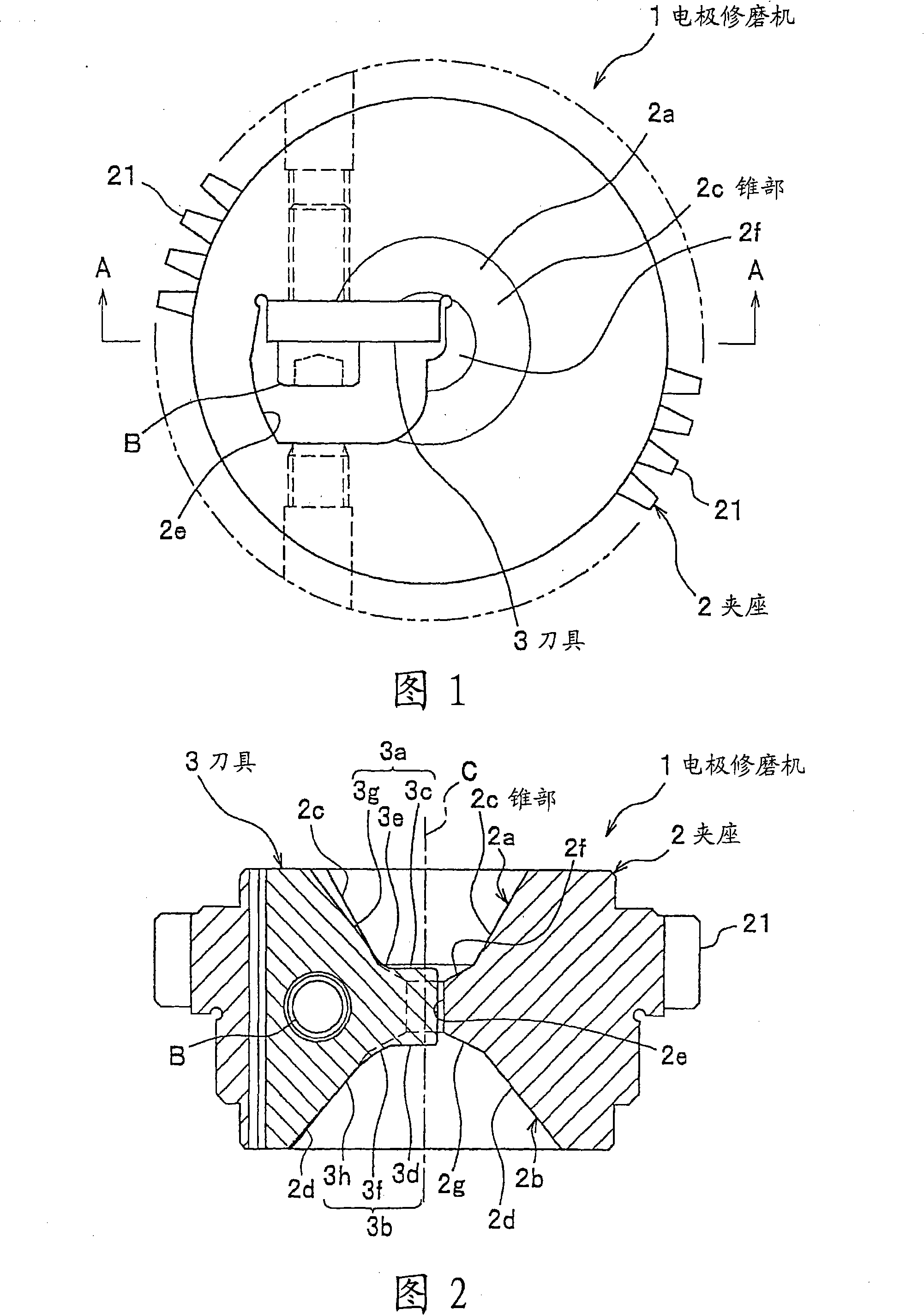
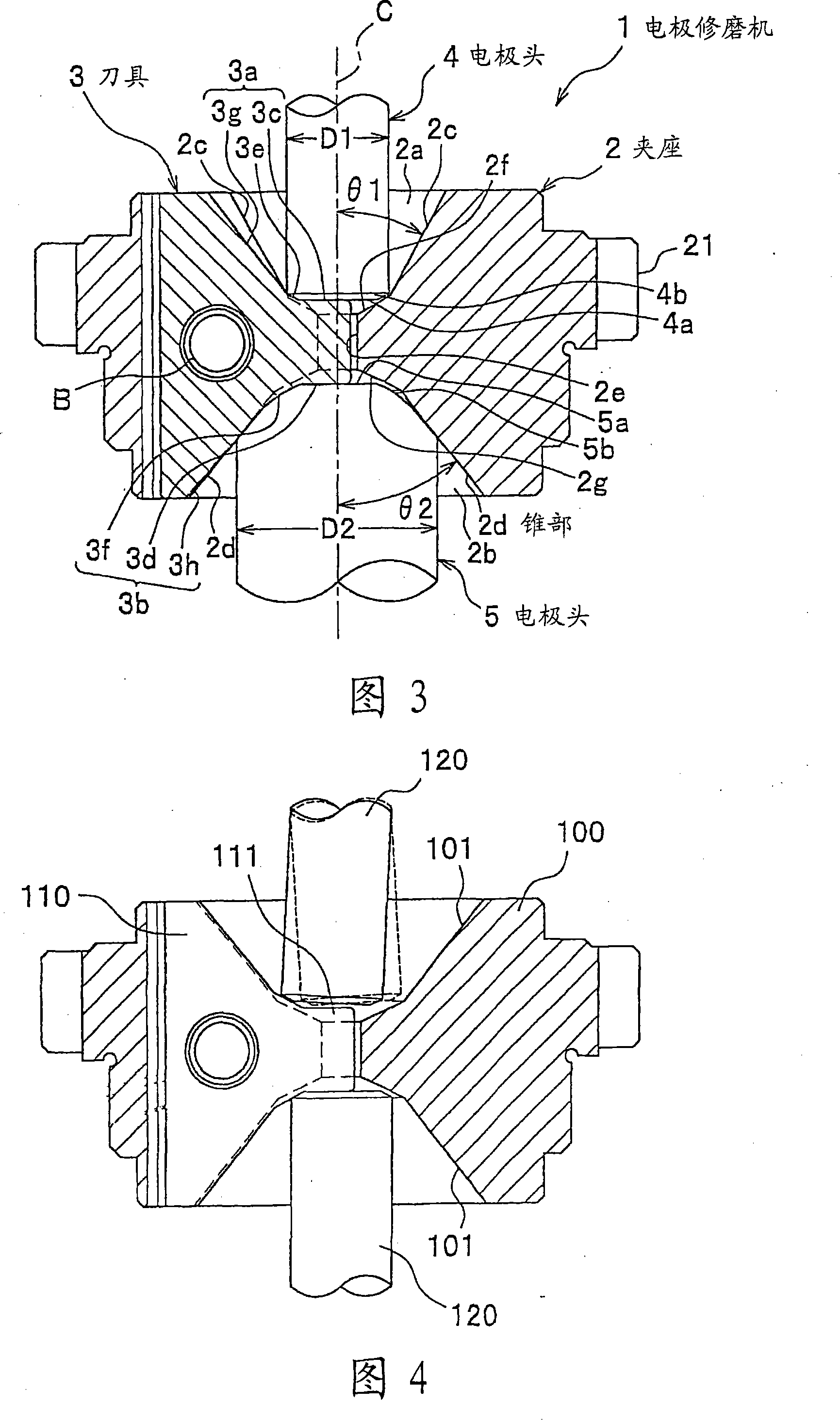
[0027] FIG. 1 is a plan view of an electrode dresser according to an embodiment of the present invention. Fig. 2 is a cross-sectional view along line A-A of Fig. 1 . 3 is a cross-sectional view showing a state in which an electrode tip is cut by the dresser according to the embodiment of the present invention.

[0028] (Structure of electrode dresser)

[0029] The electrode dresser 1 shown in FIG. 1 is a device as follows: a motor (not shown) using compressed air, oil pressure, and electricity as a driving source is connected to a chuck 2 via a transmission gear (not shown). The integral gear 21 rotates, and the tip end portions of the electrode tips 4 and 5 (see FIG. 3 ) are cut and shaped by the cutter 3 attached to the holder 2 .

[0030] (Clamp structure)

[0031] As shown in FIGS. 1 and 2 , the holder 2 is a member for holding the tool 3 and rotati...


PUM


Abstract

A tip dresser 1 dresses electrode tips 4, 5. The tip dresser 1 is rotated around a rotation axis and includes a holder 2 configured to be rotated around a rotation axis and to have concave tapers 2c, 2d, which make the rotation axis a center, on both faces of the holder 2; and a cutter 3 configured to be fixed to the holder 2 and to be protruded to sides of the electrode tips 4, 5 from the tapers 2c, 2d only at portions of the cutter 3 more inside than outer diameters D1, D2 of the electrode tips 4, 5.

Description

technical field [0001] The present invention relates to an electrode dresser for shaping an electrode tip used in spot welding, and more particularly to an electrode dresser capable of preventing radial runout of the electrode tip during shaping. Background technique [0002] Conventionally, as a dresser for shaping an electrode tip used in spot welding, there is a dresser in which a tool is fixed to a rotating chuck to cut the tip of the electrode tip. [0003] 4 is a cross-sectional view showing a state in which an electrode tip is cut by a conventional dresser. [0004] For example, as shown in FIG. 4 , there is known such an electrode grinder: there are concave tapered surfaces 101 on the upper and lower surfaces of the holder 100, and the cutter 110 is fixed on the holder 100 by screws. In this electrode dressing mechanism, the blade portion 111 of the cutter 110 slightly protrudes from the surface of the tapered surface 101 , and when the holder 100 rotates, the blade...

Claims


Application Information

Patent Timeline
IPC IPC(8): B23K11/30
CPCB23K11/3063Y10T409/304256Y10T407/1924
Inventor 后藤正星野伸二
Owner HONDA MOTOR CO LTD
Why Eureka
Try Eureka