Tip dresser

A grinding machine, electrode technology, applied in the direction of electrode characteristics, electrode maintenance, manufacturing tools, etc., can solve the problems of different conditions, unable to suppress the radial vibration of the electrode head, etc., to achieve the effect of preventing radial vibration

Inactive Publication Date: 2010-09-22
HONDA MOTOR CO LTD
View PDF3 Cites 0 Cited by
  • Summary
  • Abstract
  • Description
  • Claims
  • Application Information

AI Technical Summary

Problems solved by technology

[0007] However, in the above-mentioned electrode dresser with two cutters, if the diameter, length, and cutting amount of the upper and lower electrode tips are equal, the cutting resistance will cancel each other out, but in fact the conditions are different, so there is no way to suppress the electrode tip. The radial runout problem of

Method used


Image

  • Tip dresser
  • Tip dresser
  • Tip dresser

Examples


Embodiment Construction

[0026] Below, while referring to Figure 1 ~ Figure 3 , while describing in detail the embodiments of the present invention.

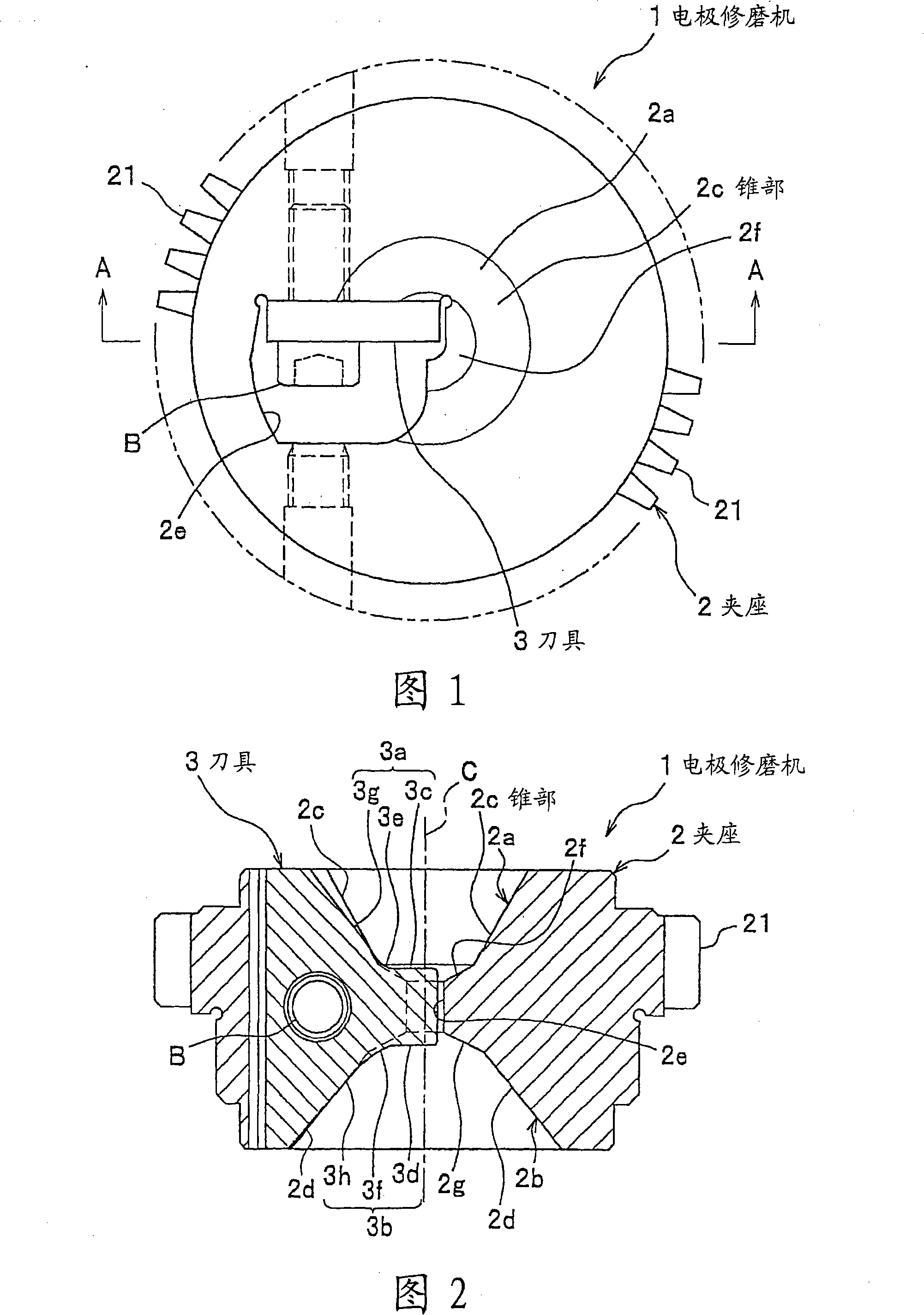
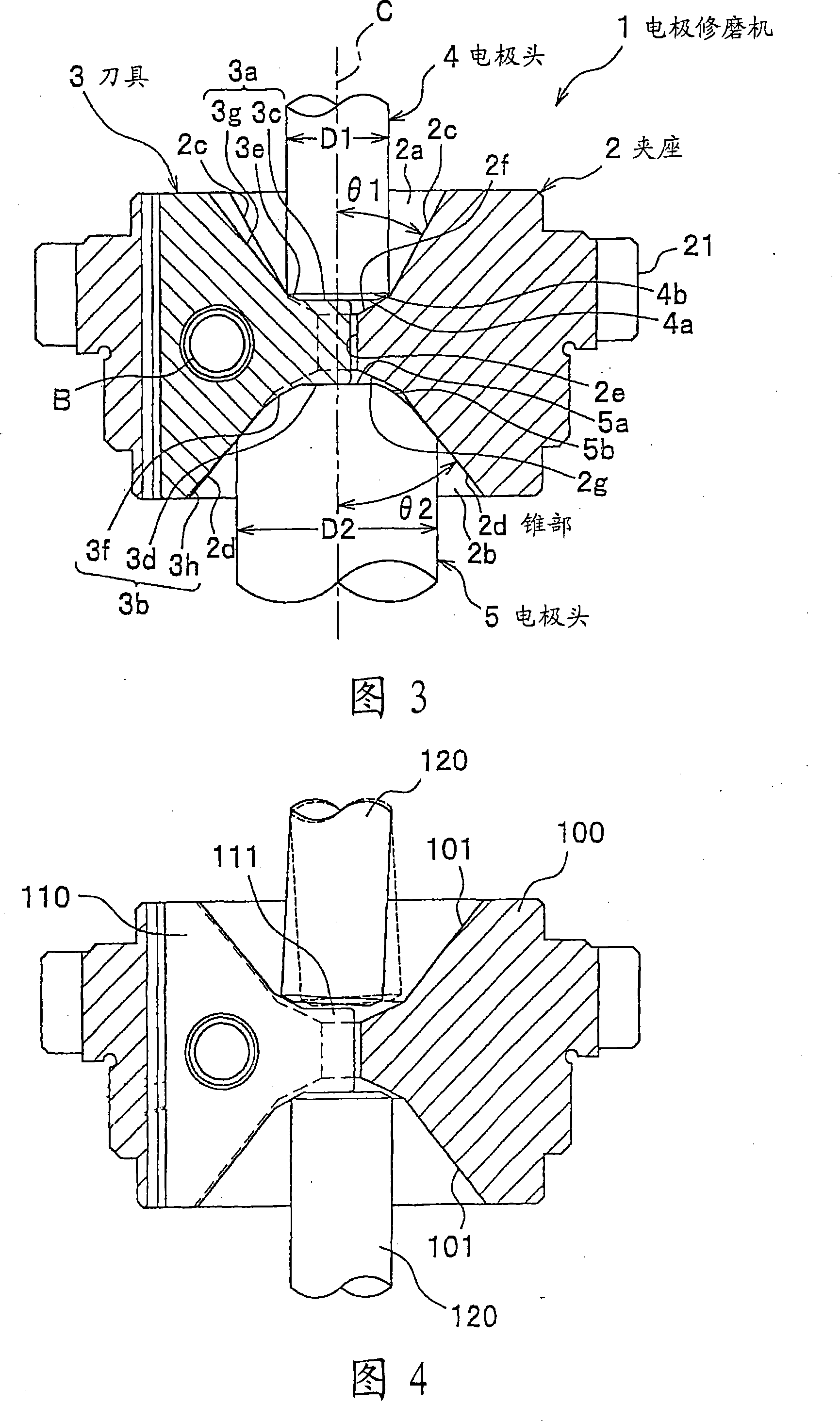
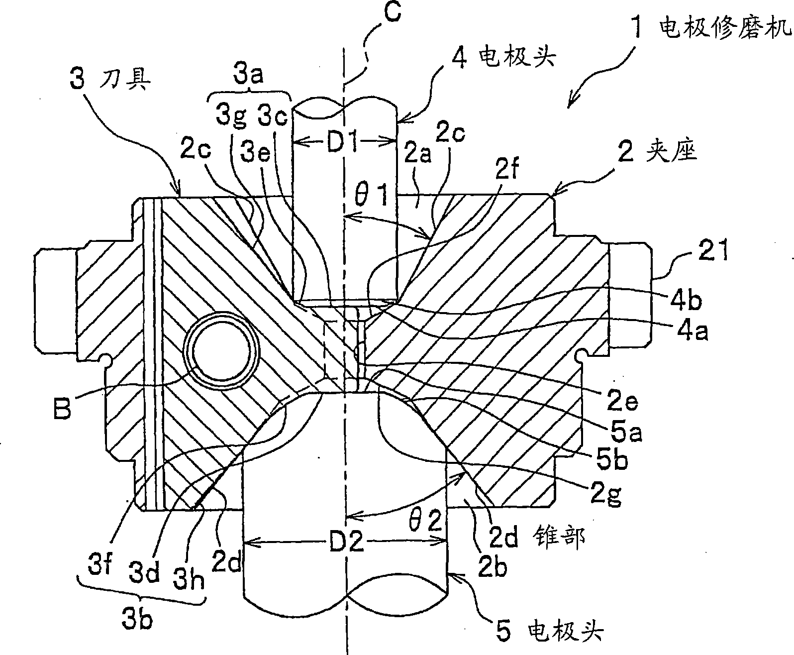
[0027] figure 1 It is a plan view of the dresser according to the embodiment of the present invention. figure 2 is along figure 1 Sectional view of line A-A. image 3 It is a cross-sectional view showing a state in which an electrode tip is cut by the dresser according to the embodiment of the present invention.

[0028] (Structure of electrode dresser)

[0029] figure 1 The electrode dresser 1 shown is a device as follows: an electric motor (not shown) using compressed air, oil pressure, and electricity as a driving source drives a motor (not shown) integrated with a holder 2 via a transmission gear (not shown). The gear 21 rotates, and the cutter 3 opposite electrode tips 4,5 (referring to image 3 ) for cutting and shaping.

[0030] (Clamp structure)

[0031] Such as figure 1 and figure 2 As shown, the holder 2 is a member for holdi...


PUM


Abstract

The invention provides a tip dresser (1) for reshaping electrode tips (4, 5). The tip dresser (1) comprises a holder (2) rotated around its rotating axis and having, on its both faces, recessed tapers (2c, 2d) having centers on its rotating axis and a cutter (3) fixed to the holder (2) and projected from the tapers (2c, 2d) to the electrode tip (4, 5) sides only on the inner portions of the outerdiameters (D1, D2) of the electrode tips (4, 5).

Description

technical field [0001] The present invention relates to an electrode dresser for shaping an electrode tip used in spot welding, and more particularly to an electrode dresser capable of preventing radial runout of the electrode tip during shaping. Background technique [0002] Conventionally, as a dresser for shaping an electrode tip used in spot welding, there is a dresser in which a tool is fixed to a rotating chuck to cut the tip of the electrode tip. [0003] Figure 4 It is a cross-sectional view showing a state in which an electrode tip is cut by a conventional dresser. [0004] For example, if Figure 4 As shown, there is known such an electrode dresser: there are concave tapered surfaces 101 on the upper and lower surfaces of the holder 100, and the cutter 110 is fixed on the holder 100 by screws. In this electrode dressing mechanism, the blade portion 111 of the cutter 110 slightly protrudes from the surface of the tapered surface 101 , and when the holder 100 rotat...

Claims


Application Information

Patent Timeline
Patent Type & Authority Patents(China)
IPC IPC(8): B23K11/30
CPCB23K11/3063Y10T409/304256Y10T407/1924
Inventor 后藤正星野伸二
Owner HONDA MOTOR CO LTD
Why Eureka
Try Eureka