Yarn tension monitoring and setting system

A technology of yarn tension and yarn, which is applied in control/regulation systems, transportation and packaging, textiles and papermaking, etc., and can solve the problem that yarn tension cannot be maintained sufficiently uniform

Inactive Publication Date: 2008-10-08
IRO AB
View PDF5 Cites 7 Cited by
  • Summary
  • Abstract
  • Description
  • Claims
  • Application Information

AI Technical Summary

Problems solved by technology

Yarn tension does not remain suffic

Method used


Image

  • Yarn tension monitoring and setting system
  • Yarn tension monitoring and setting system

Examples


Embodiment Construction

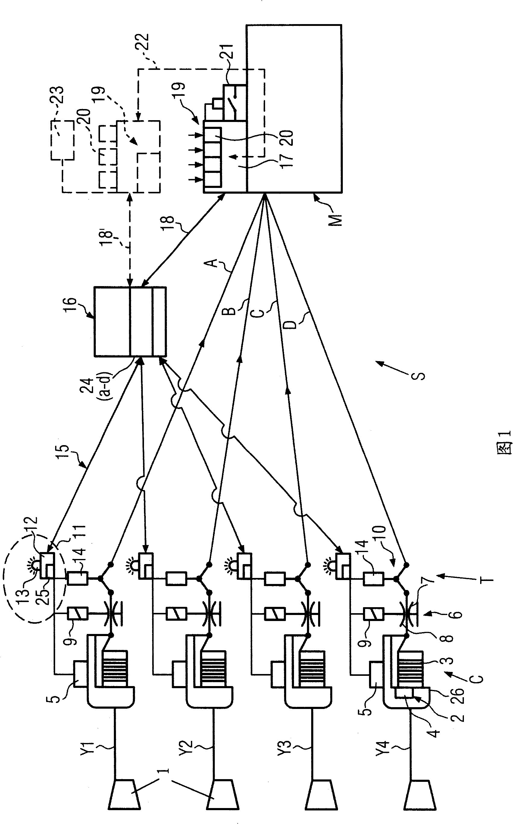
[0028] A yarn processing machine M, such as a yarn twisting machine, a crimper such as an air-jet entangler, or a printing and dyeing machine, simultaneously processes a plurality of yarns Y1 to Y4 (or even more) Separate yarn channels A to D run into a common inlet or into several inlets of the yarn processing machine M. Between eg a series of yarn storage coils 1 and a yarn processing machine M, a yarn delivery device C and a yarn tensioning device T are arranged. The yarn delivery device C is split into a corresponding number of conveyors, each of which corresponds to only a single yarn Y1 to Y4 , such as the yarn feeding device 2 . Each yarn feeding device may be a yarn feeding device normally used for rapier looms or projectile looms. The respective yarn feeding device 2 has a fixed storage drum 3 , an electric motor 4 for driving the winding element 26 and an integrated speed controller 5 .

[0029] Similarly, the thread tensioning device T is split into a correspondin...


PUM


Abstract

Yarn processing system (S) for simultaneously processing a plurality of yarns (Y1) to (Y4) in a processing machine, such as a twisting machine, a texturising machine, or a dyeing machine. A yarn tensioning assembly is provided and has, for each yarn entering the processing machine (M), at least an individual controlled tensioner (6) and an individual tensiometer (10). The controlled tensioner (6)and the tensiometer (10) are integrated into a closed yarn tension feedback regulation loop (11) for regulating and maintaining a set yarn tension. The tensiometer (10) is connected in parallel to one superimposed common tension monitoring and setting system (19) for centrally setting and monitoring the yarn tension.

Description

technical field [0001] The invention relates to a yarn handling system according to the preamble of claim 1 . Background technique [0002] EP0644957A, NL1022975A, US-A-4778118 and JP-A10310329 relate to yarn handling systems using a common delivery device and a common yarn tensioning device for a plurality of yarns running simultaneously. The individual processors are twisters or crimpers (air-jet entanglers) or spinners. JP-A-10310329 discloses, for example, an individual yarn detector and a common signal evaluation device for signaling a yarn breakage. The common transfer device and the yarn tensioning device must guarantee a completely uniform yarn tension between the simultaneously processed yarns. The yarn tension cannot be adjusted individually for each yarn. Inevitably, however, variations in yarn tension that occur between yarns obviously have undesired effects on the final product quality. Furthermore, the individual yarn detectors required require relatively h...

Claims


Application Information

Patent Timeline
IPC IPC(8): B65H59/10B65H59/40B65H63/02B65H63/04D01H13/10D02G1/10D06B23/00G05D15/01
CPCB65H59/387B65H2701/31B65H63/04B65H63/02B65H59/06
Inventor 斯特凡诺·兰普里洛
Owner IRO AB
Why Eureka
Try Eureka