Process for manufacturing vacuum cartridge fuse

A fuse tube and manufacturing process technology, applied in the direction of fuse manufacturing, manufacturing tools, emergency protection devices, etc., to achieve the effects of good time consistency, good anti-knock performance, and shortened production time

Active Publication Date: 2011-06-29
DONGGUAN BETTER ELECTRONICS TECH +1
View PDF1 Cites 0 Cited by
  • Summary
  • Abstract
  • Description
  • Claims
  • Application Information

AI Technical Summary

Problems solved by technology

[0006] The purpose of the present invention is to solve the above-mentioned deficiencies of the existing fuse tubes in terms of performance and service life, and provide a manufacturing process of vacuum fuse tubes - a high-frequency welding process of vacuum fuse tubes and its specific operation steps

Method used


Image

  • Process for manufacturing vacuum cartridge fuse
  • Process for manufacturing vacuum cartridge fuse
  • Process for manufacturing vacuum cartridge fuse

Examples


Embodiment 1

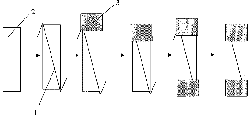
[0042] Combination hint figure 2, 4. First, carry out step A (not shown in the figure), and fix the pipe body 2 on the positioning fixture 4. In this embodiment, in the step B, first place the fuse 1 obliquely in the pipe body 2, and make the Both ends of the fuse 1 are exposed on the outside of the tube body 2; then the exposed two ends are bent outward along the end surface of the tube body 2, that is, the fuse 1 is bent into a "Z" shape. Then put the tinned copper cap 3 on one end of the pipe body, put the pipe body 3 with the copper cap 3 together with the positioning fixture 4 into the openable airtight welding cavity 5 of the high-frequency welding machine, and open the high-frequency welding machine. Frequency welding machine for 1-5 seconds, weld the copper cap at this end; take out the positioning fixture 4, put the copper cap on the other end of the pipe body 2, put them together into the airtight welding cavity 5, and use the pump to seal the airtight welding cavit...

Embodiment 2

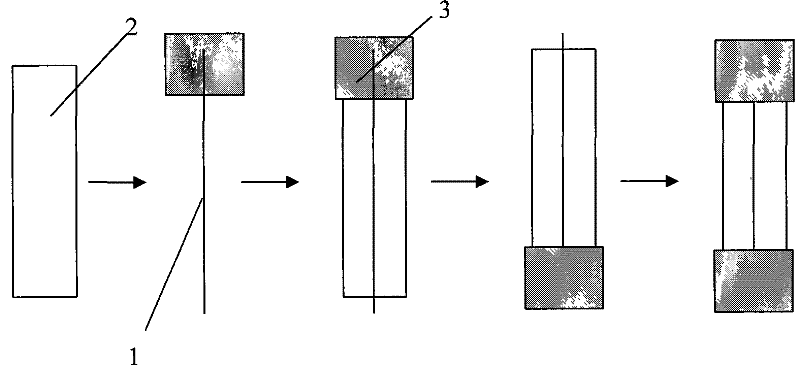
[0044] Combination hint image 3 , 4. First, carry out step A (not shown in the figure), and fix the pipe body 2 on the positioning fixture 4. In this embodiment, steps B and C are combined, that is, the fuse 1 is vertically fixed on the copper cap 3 through tin in advance. Then put the copper cap 3 on the tube body 2 while passing the fuse through the tube body 2, and put the tube body 3 with the copper cap 3 together with the positioning fixture 4 into the openable Open the high-frequency welding machine for 1 to 5 seconds, and weld the copper cap at this end; after taking it out, put another copper cap on it, put it into the sealed welding cavity again, and put the closed welding cap into the closed welding cavity. Cavity 5 is evacuated into a vacuum state by an air extraction device, and then the high-frequency welding machine is turned on for 1 to 5 seconds to complete the welding of the copper cap at the other end and take it out.


PUM


Abstract

The present invention relates to a cartridge fuse and a manufacturing technique for the cartridge fuse, in particular to a vacuum cartridge fuse and a manufacturing technique for the cartridge fuse. The interior of main body of the cartridge fuse is in vacuum state. The present invention utilizes high frequency welding technique to solder a fuse, a tube, and a tinned copper cap together as follows: high frequency current is provided by a high frequency welding machine, an enclosed soldering cavity that can be opened is arranged, alternating magnetic field is produced by the high frequency current in the enclosed soldering cavity, the frequency and time of the high frequency current is controlled, so that the tin on the tinned cap is melted and therefore the soldering is completed in the enclosed soldering cavity. The copper cap on one end is soldered with high frequency welding technique; before the other end is soldered, the cavity is pumped into vacuum state to attain the purpose ofprotecting the finished product of cartridge fuse.

Description

Technical field: [0001] The invention relates to the technical field of fuse tube and its manufacture, in particular to a manufacturing process of a vacuum fuse tube. Background technique: [0002] Due to the limitations of the design and the welding process of the existing fuse tube, the inside of the tube is not vacuum after welding, and the inside is usually filled with air. Fuse products are generally used in live circuits. Under long-term energized conditions, they will generate temperature themselves. Under this temperature condition, if the fuse is in an environment with air around it, because the moisture and oxygen in the air will And so on, the fuse will be corroded, which will affect the life of this product. In addition, the fuse tube generates a lot of heat when it is blown, causing the surrounding medium to expand, so it is prone to explosion hazards; moreover, when the product works in the circuit, it will generate heat, and the heat is usually transmitted in...

Claims


Application Information

Patent Timeline
Patent Type & Authority Patents(China)
IPC IPC(8): H01H85/045H01H69/02B23K13/00B23K13/06
Inventor 韩露高连忠
Owner DONGGUAN BETTER ELECTRONICS TECH
Why Eureka
Try Eureka