Suction head apparatus

A technology of control devices and suction pads, applied in the direction of chucks, manipulators, electrical components, etc., can solve problems such as bulky, complex structures, difficult to meet space saving, intensification and miniaturization

Active Publication Date: 2008-10-08
HIRATA & CO LTD
View PDF2 Cites 22 Cited by
  • Summary
  • Abstract
  • Description
  • Claims
  • Application Information

AI Technical Summary

Problems solved by technology

[0008] However, in this suction head device, the mechanism for raising and lowering the nozzle shaft includes a cam member having a rotating shaft in the horizontal direction, a rod-shaped member, a link member, etc., and a mechanism for preventing the nozzle shaft from falling due to its own w...

Method used


Image

  • Suction head apparatus
  • Suction head apparatus
  • Suction head apparatus

Examples


Embodiment Construction

[0036] Hereinafter, preferred embodiments of the present invention will be described with reference to the drawings.

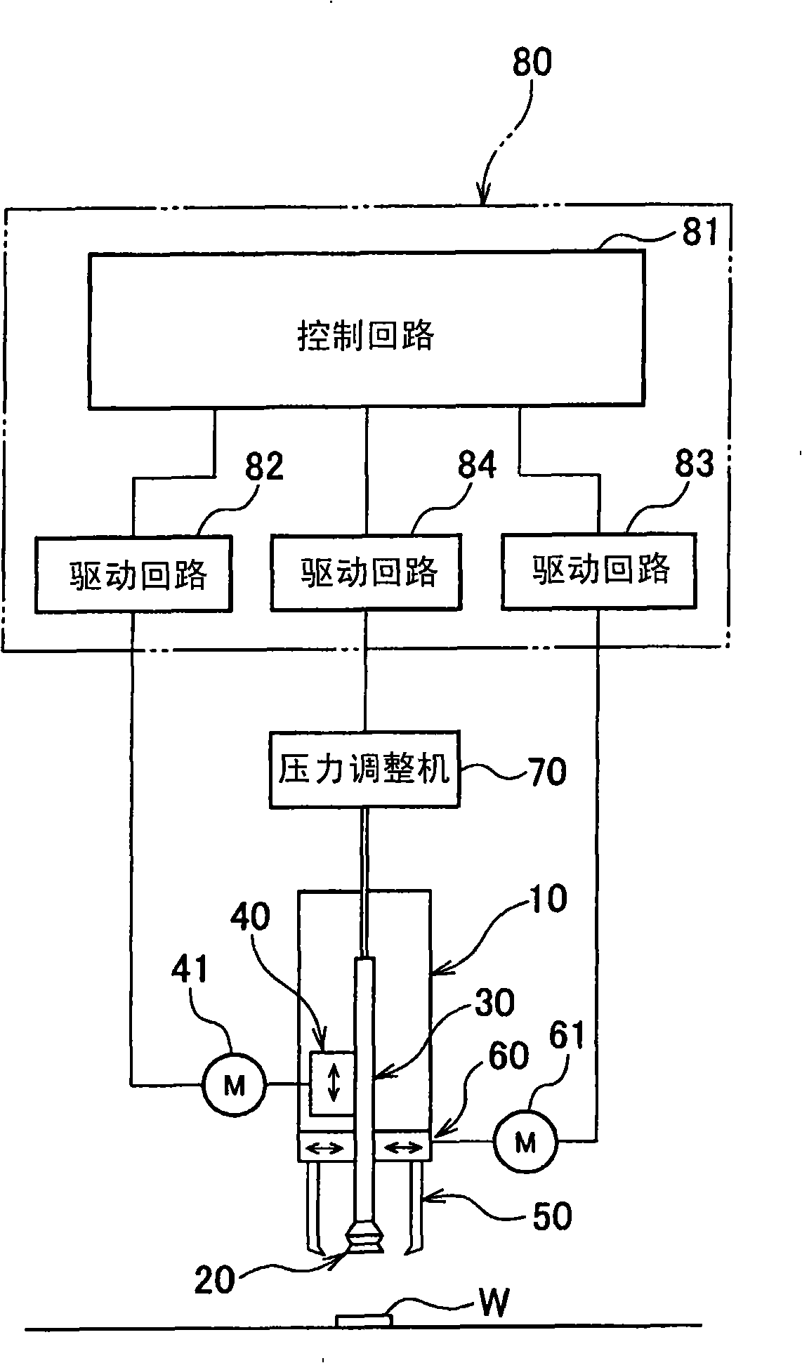
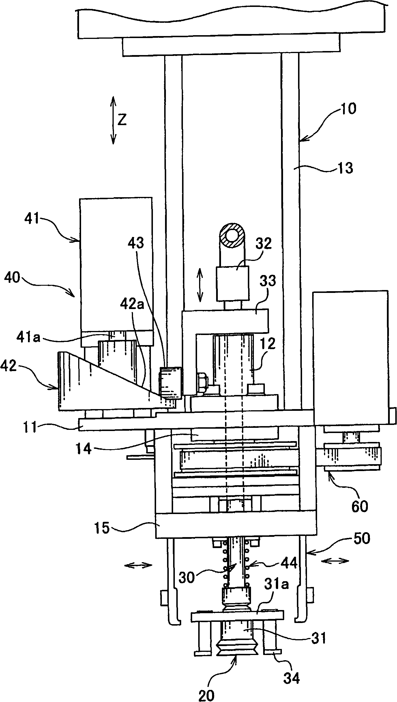
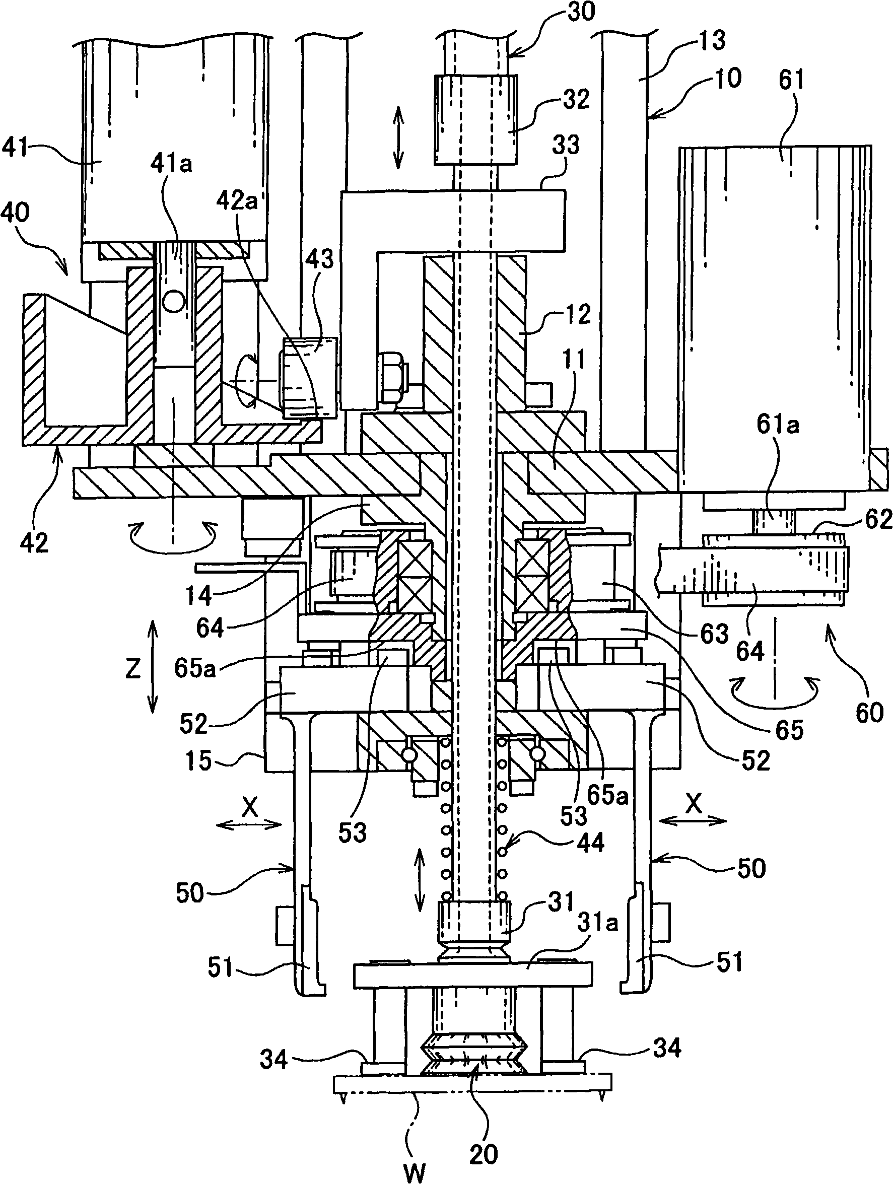
[0037] like Figure 1 to Figure 3As shown, the suction head device includes: a basic frame 10 for the structure; a suction pad 20 for absorbing the workpiece W; a shaft 30 for holding the suction pad 20 at its lower end and moving up and down; a lifting mechanism 40 for lifting the shaft 30; Two pairs of clamping arms 50 and a drive mechanism 60 as a clamping mechanism for clamping the workpiece W absorbed by the suction pad 20 from a substantially horizontal direction; a pressure regulator 70 as a suction generating mechanism for generating suction on the suction pad 20 ; and the control unit 80 etc. as a control device that controls the drive control of the entire device.

[0038] In addition, this suction head device is used as a workpiece transfer device that absorbs a workpiece W conveyed by a conveyor belt and transfers it to a predetermined processing ...


PUM


Abstract

A suction head device has a suction pad (20) for sucking a workpiece (W), a suction force generation device (70) for making the suction pad (20) generate suction force, a shaft (30) for holding at its lower end the suction head (20) and vertically moving suction head, a lifting mechanism (40) for lifting and lowering the shaft (30), holding mechanisms (50, 60) for holding the workpiece (W), sucked by the suction pad (20), from horizontal directions, and a control means (80) for driving and controlling the suction force generation mechanism (70) such that, after the workpiece (W) is held by the holding mechanisms (50, 60), the suction by the suction pad (20) is once released and then the suction pad (20) is again caused to suck the workpiece (W).; Even if holding by the holding mechanisms and suction by the suction pad are sequentially released, the workpiece is reliably transferred while being highly accurately positioned.

Description

technical field [0001] The present invention relates to a suction head device for suctioning and transporting workpieces such as semiconductor-related electronic devices or mechanical parts, and more particularly to a suction head for positioning and transporting workpieces to predetermined positions while suctioning and taking them out from a storage position. device. Background technique [0002] In the production line of semiconductors or other tiny electronic devices, etc., workpieces (electronic devices) as objects are conveyed by conveyor belts to various processing stages, and are taken out from the conveyor belts by transfer devices and transferred to the processing section The prescribed processing is carried out at the prescribed location. [0003] However, for such workpieces (electronic devices), since the life cycle of products using these workpieces is short, frequent model changes are required. Therefore, corresponding to this model change, in order to manuf...

Claims


Application Information

Patent Timeline
IPC IPC(8): B25J15/06
CPCB25J15/0206H05K13/0465B25J15/0616H05K13/0408B25J15/028H05K13/0409H05K13/0413
Inventor 渡边敏彦田野实贵彦
Owner HIRATA & CO LTD
Why Eureka
Try Eureka