

Yagi antenna of electric-controlled plasma
A technology of plasma and Yagi antennas, applied in antennas, antenna supports/mounting devices, electrical components, etc., can solve the problems of poor stealth performance of metal Yagi antennas, non-directionality of Yagi antennas, and large radar scattering cross-section, etc., to achieve The effect of simple and easy structure, light weight and little interference
Inactive Publication Date: 2008-10-15
NANJING UNIV OF AERONAUTICS & ASTRONAUTICS
View PDF0 Cites 7 Cited by
- Summary
- Abstract
- Description
- Claims
- Application Information
AI Technical Summary
Problems solved by technology
Because metal has a strong ability to reflect electromagnetic waves, its radar scattering cross section is relatively large, resulting in poor stealth performance of traditional metal Yagi antennas and low survivability in electronic warfare
After the traditional Yagi antenna is installed, its radiation direction is certain. If you want to change its radiation direction, you must manually or mechanically adjust the position and polarization direction of the antenna. The sensitivity is low and the failure rate is high.
So the traditional Yagi antenna does not have flexible directivity
Method used
View moreImage
Smart ImageViewing Examples

Examples
Embodiment Construction
Login to View More PUM
 Abstract
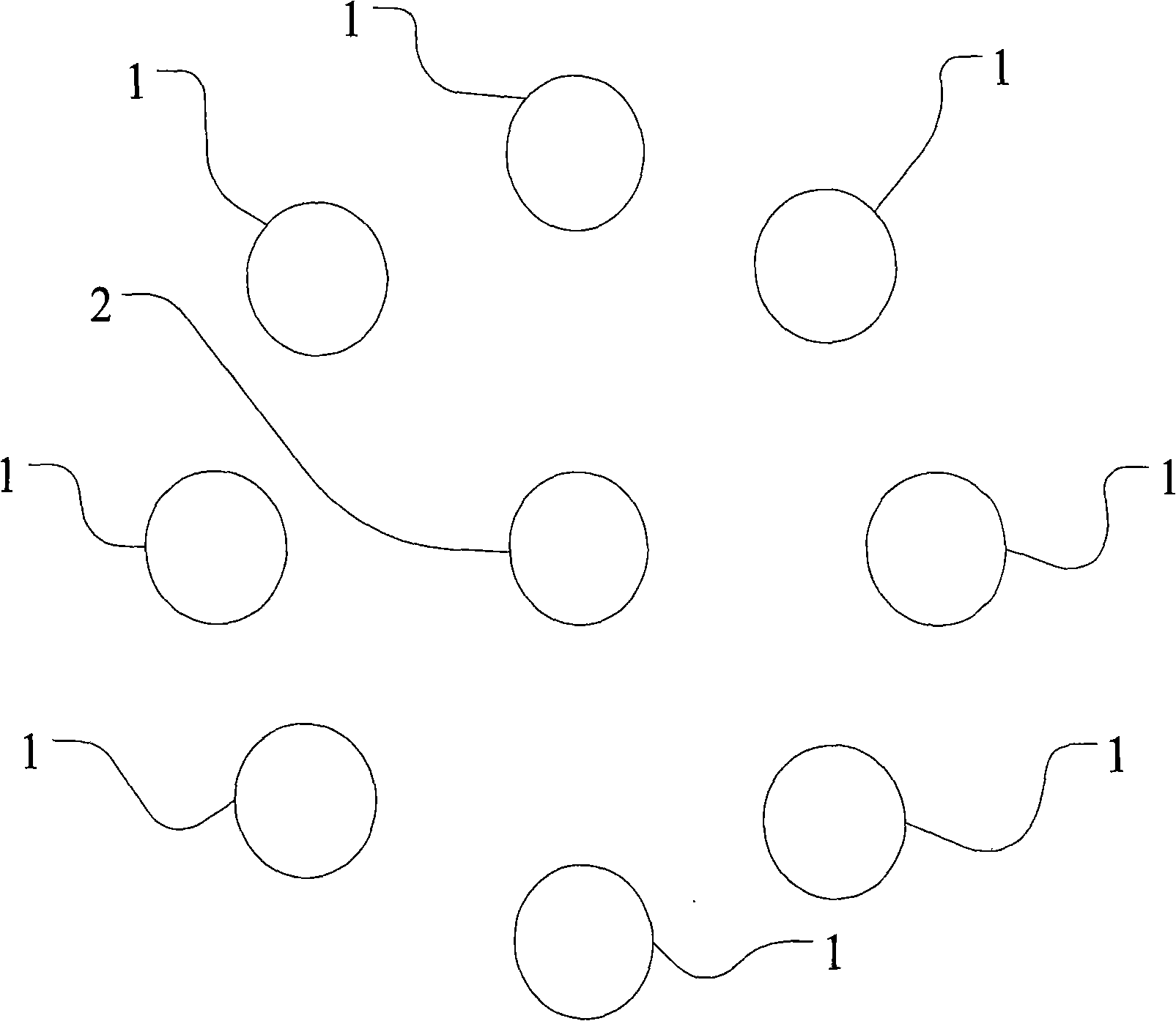
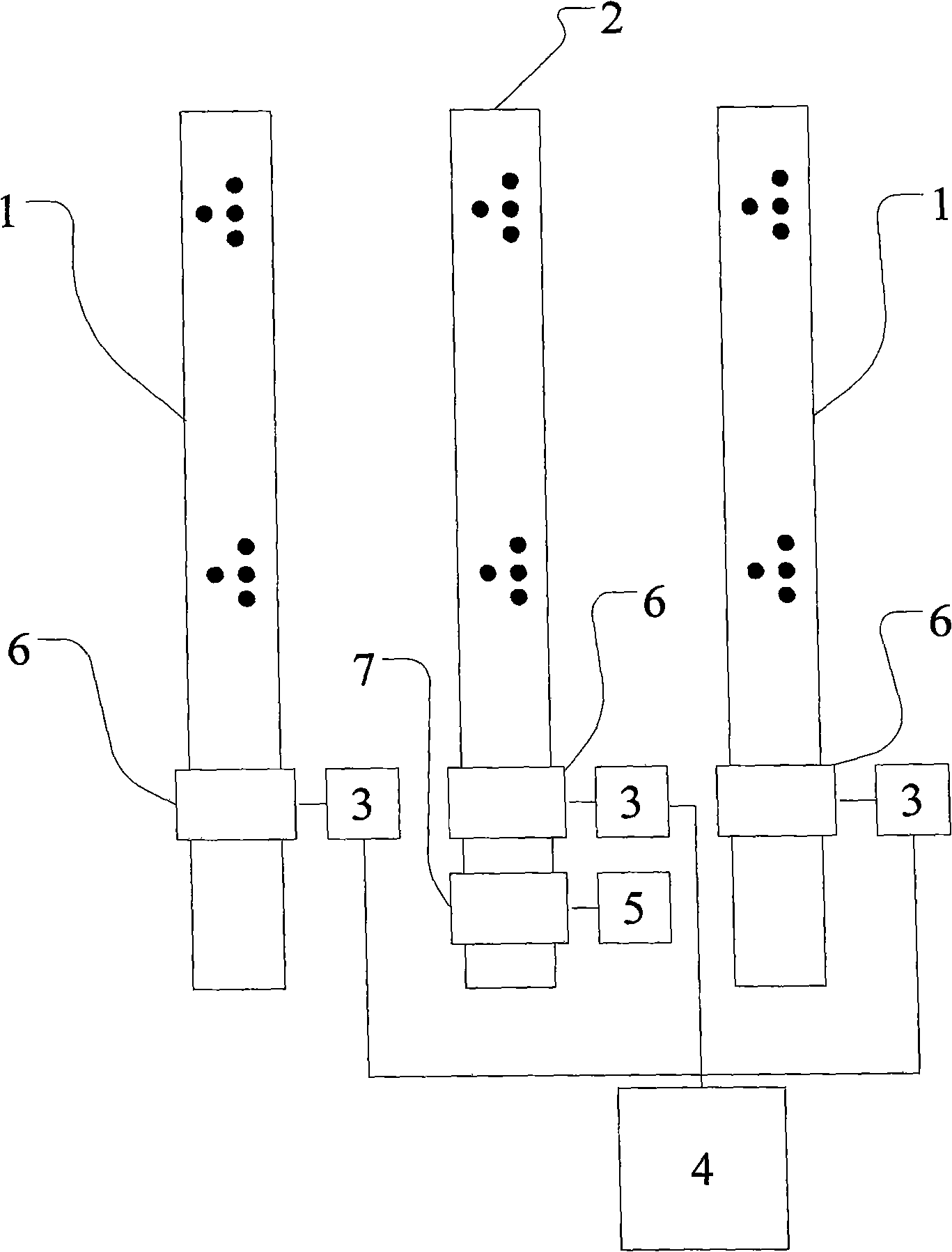
The invention discloses an electrically-controlled plasma yagi-uda antenna, belonging to the technical field of antennae, which is characterized in that: the electrically-controlled plasma yagi-uda antenna comprises an active dipole at the center, and reflecting / director dipoles in ring shape and symmetrically arrayed at the periphery of the active dipole. The number of the reflecting / director dipoles is 2N (N represents a natural number that is more than or equal to 1). The reflecting / director dipoles can act as both reflecting dipoles and director dipoles, wherein, every two reflecting / director dipoles which are centrosymmetric with the active dipole are a pair of reflecting dipoles and a pair of director dipoles. Within a same period, only one pair of the reflecting dipoles and the director dipoles are in working states. The electronically-controlled plasma yagi-uda antenna is provided with flexible directionality.
Description
Electronically Controlled Plasma Yagi Antenna Technical field The invention relates to an antenna used in the technical field of communication, in particular to an electronically controlled plasma Yagi antenna. Background technique Yagi antenna, also known as directional antenna, is an antenna jointly developed and invented by Yagi Hideji and Uda Shintaro of Tohoku University in Japan in the 1920s, so it is called Yagi-Uda antenna, or Yagi antenna for short. Because the Yagi antenna has good directivity and has higher gain than the dipole antenna, it is widely used in radio equipment such as meter wave and decimeter wave band communication, TV, etc., for distance measurement and long-distance communication . In recent years, the military application of meter wave Yagi antenna has attracted much attention. It is mainly used as radar antenna for the identification of invisible targets and electronic countermeasures. The Yagi antenna generally consists of a reflecting osc...
Claims
Login to View More Application Information
Patent Timeline
 Patent Type & AuthorityApplications(China)
IPC IPC(8): H01Q1/26H01Q19/30
Inventor刘少斌尹昌刚
OwnerNANJING UNIV OF AERONAUTICS & ASTRONAUTICS