Radial multi-beam gap waveguide slot antenna array applied to microwave band

A technology of gap waveguide and slot antenna, which is applied in the direction of separately energized antenna array, antenna array, antenna, etc., can solve the problems of unsatisfactory and difficult antenna beam control, etc., and achieve simple processing, outstanding low loss effect, and easy realization Effect

Active Publication Date: 2019-07-26
SOUTHEAST UNIV
View PDF5 Cites 2 Cited by
  • Summary
  • Abstract
  • Description
  • Claims
  • Application Information

AI Technical Summary

Problems solved by technology

This kind of antenna is difficult to achieve flexible beam control, and cannot meet the needs

Method used


Image

  • Radial multi-beam gap waveguide slot antenna array applied to microwave band
  • Radial multi-beam gap waveguide slot antenna array applied to microwave band
  • Radial multi-beam gap waveguide slot antenna array applied to microwave band

Examples


Embodiment Construction

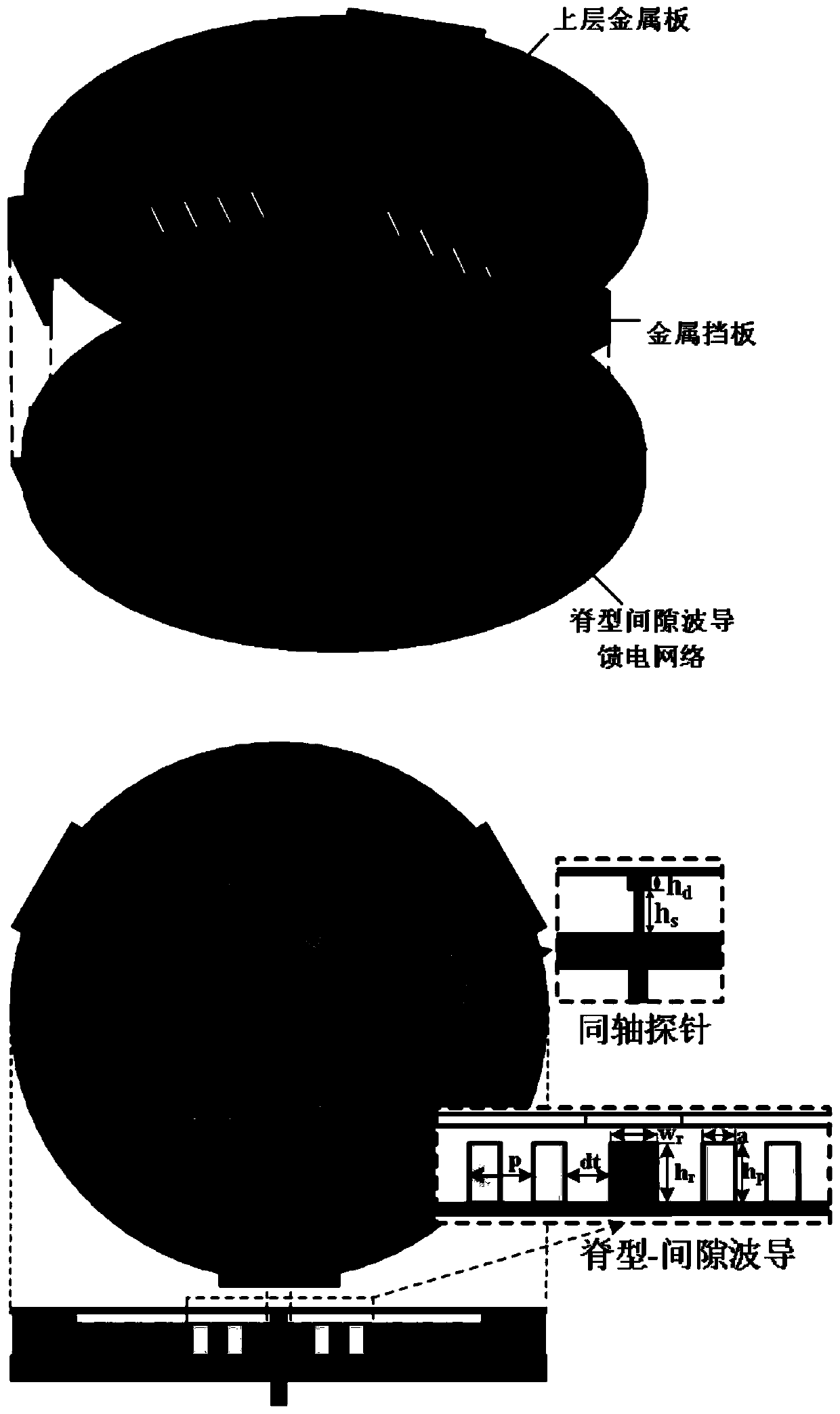
[0053] Such as figure 2 As shown, a radial multi-beam gap waveguide slot antenna array applied to the microwave segment includes three parts: the gap waveguide radial feed network, the slot antenna array and the "coaxial-gap waveguide" conversion structure.

[0054] Wherein, the radial 1:N (N is a non-zero positive integer) feeding network of the gap waveguide includes a circular metal plate, an air gap, a radial metal ridge, an electromagnetic bandgap structure and a circular metal floor arranged in sequence. The number N of shunts is determined by the number of metal ridges laid along the radial direction of the circle; no less than one row of electromagnetic bandgap structural units are laid on both ends of each metal ridge to limit the propagation direction of the wave; The ridge-gap waveguide feeding network is used to transmit the "quasi-TEM" mode; the structure confines the wave propagation to the air gap between the ridge and the top circular metal plate, and the wave...


PUM

PropertyMeasurementUnit
Radiusaaaaaaaaaa
Thicknessaaaaaaaaaa

Abstract

The invention discloses a radial multi-beam gap waveguide slot antenna array applied to a microwave band. The radial multi-beam gap waveguide slot antenna array comprises three parts of a gap waveguide radial feeding network, a slot antenna array and a coaxial-gap waveguide conversion structure. By a design of a bottom-layer feeding network and each slot sub-array in a top layer in a radial direction, generation of random numbers of radial wave beams can be achieved, the size and the direction of each wave beam are independently adjustable, and a beam split phenomenon is proposed according toa certain radial asymmetric construction mode of the antenna.

Description

technical field [0001] The invention relates to the technical field of antennas, in particular to a radial multi-beam gap waveguide slot antenna array applied in the microwave section. Background technique [0002] Gap waveguide is a new type of low-loss transmission line proposed based on the definition of artificial soft and hard surfaces by P.S.Kildal in 1988. There are three types of transmission lines: ridge gap waveguides, microstrip gap waveguides, and slot gap waveguides. The field of the gap waveguide propagates along the metal ridge, metal strip or metal groove to form a passband; on both sides of the passband are ideal magnetic conductor surfaces composed of artificial magnetic conductor structures or electromagnetic bandgap structures, which combine with the upper layer of ideal electric conductor surfaces to form a The stopband, which causes the wave to propagate along the passband path considered designed. This waveguide structure was first proposed to solve ...

Claims


Application Information

Patent Timeline
IPC IPC(8): H01Q1/36H01Q1/50H01Q15/00H01Q21/00H01Q21/06
CPCH01Q1/36H01Q1/50H01Q15/0086H01Q21/0006H01Q21/064
Inventor 崔铁军穆竟
Owner SOUTHEAST UNIV
Why Eureka
Try Eureka