Radar antenna

A technology of radar antenna and antenna, which is applied in the direction of antenna coupling, resonant antenna, antenna support/installation device, etc., can solve the problems of wrong estimation of target position or angle value, error of radar antenna angle measurement result, antenna pattern distortion, etc. Achieve the effects of improving smoothness, improving angle measurement accuracy, and reducing radar scattering cross section

Pending Publication Date: 2021-11-02
CHINA AUTOMOTIVE INNOVATION CORP
View PDF5 Cites 2 Cited by
  • Summary
  • Abstract
  • Description
  • Claims
  • Application Information

AI Technical Summary

Problems solved by technology

However, when the radar is in use, the installation position of the radar causes multiple reflections of the electromagnetic waves radiated by the radar. The multiple reflected signals may lead to misestimation of the target position or angle value, and the surrounding materials will reflect the electromagnetic waves radiated by the radar. In addition, The surface wave of the radar antenna can propagate along the surface of the medium to the outside of the radiation antenna, and radiate when it encounters a discontinuity point, causing the antenna pattern to be distorted, making the azimuth plane gain curve of the antenna fluctuate greatly, resulting in the angle measurement of the radar antenna The result error is large

Method used


Image

  • Radar antenna
  • Radar antenna
  • Radar antenna

Examples


Embodiment Construction

[0029] In order to enable those skilled in the art to better understand the technical solutions in the present application, the technical solutions in the embodiments of the present application will be clearly and completely described below in conjunction with the drawings in the embodiments of the present application. Obviously, the described The embodiments are only some of the embodiments of the present application, but not all of them. Based on the embodiments in this application, all other embodiments obtained by persons of ordinary skill in the art without creative efforts shall fall within the scope of protection of this application.

[0030] It should be noted that the terms "first" and "second" in the description and claims of the present invention and the above drawings are used to distinguish similar objects, but not necessarily used to describe a specific sequence or sequence. It is to be understood that the data so used are interchangeable under appropriate circum...


PUM


Abstract

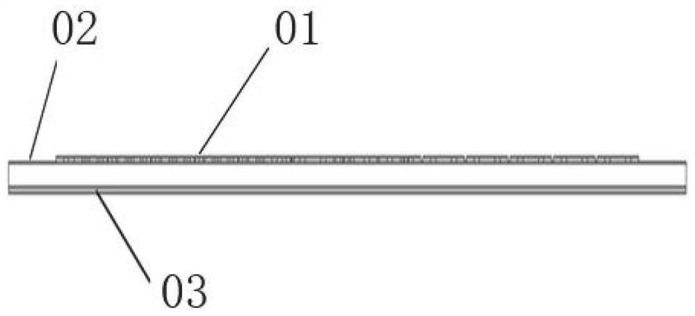
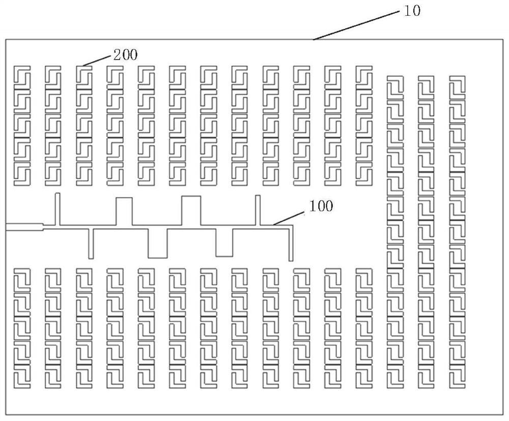
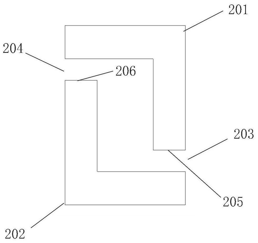
The invention discloses a radar antenna, which is characterized in that a plurality of metal patches are arranged around an antenna unit, each metal patch comprises a first metal unit and a second metal unit, the first metal unit and the second metal unit are both L-shaped structures, and the first metal unit and the second metal unit form a square structure with gaps at opposite angles. The radar cross section of the radar antenna can be reduced, antenna surface waves are suppressed, the smoothness of an azimuth plane gain curve of the radar antenna is improved, and the angle measurement precision of the radar antenna is improved.

Description

technical field [0001] The invention relates to the field of antennas, in particular to a radar antenna. Background technique [0002] With the development of science and technology, radar antennas are widely used in factory automation production, building automation, urban traffic management, automotive advanced driver assistance systems, automatic driving and many other occasions that require human-computer interaction. However, when the radar is in use, the installation position of the radar causes multiple reflections of the electromagnetic waves radiated by the radar. The multiple reflected signals may lead to misestimation of the target position or angle value, and the surrounding materials will reflect the electromagnetic waves radiated by the radar. In addition, The surface wave of the radar antenna can propagate along the surface of the medium to the outside of the radiation antenna, and radiate when it encounters a discontinuity point, causing the antenna pattern t...

Claims


Application Information

Patent Timeline
Patent Type & Authority Applications(China)
IPC IPC(8): H01Q1/36H01Q9/04H01Q1/52H01Q1/22G01S7/02
CPCH01Q1/36H01Q9/045H01Q1/52H01Q1/22G01S7/02
Inventor 李丰军周剑光张魏杨慧戚健庭
Owner CHINA AUTOMOTIVE INNOVATION CORP
Why Eureka
Try Eureka