
Wind turbine rotor blades with reduced radar cross sections

a technology of wind turbines and radars, applied in the field of wind turbines, can solve the problems of preventing the feasibility of placing wind turbines and certain locations, affecting the monitoring of space on the opposite side of such wind turbines, etc., and achieves the effects of reducing radar cross section

Active Publication Date: 2015-09-22
LM WIND POWER US TECH APS
View PDF12 Cites 3 Cited by
  • Summary
  • Abstract
  • Description
  • Claims
  • Application Information

AI Technical Summary

Benefits of technology

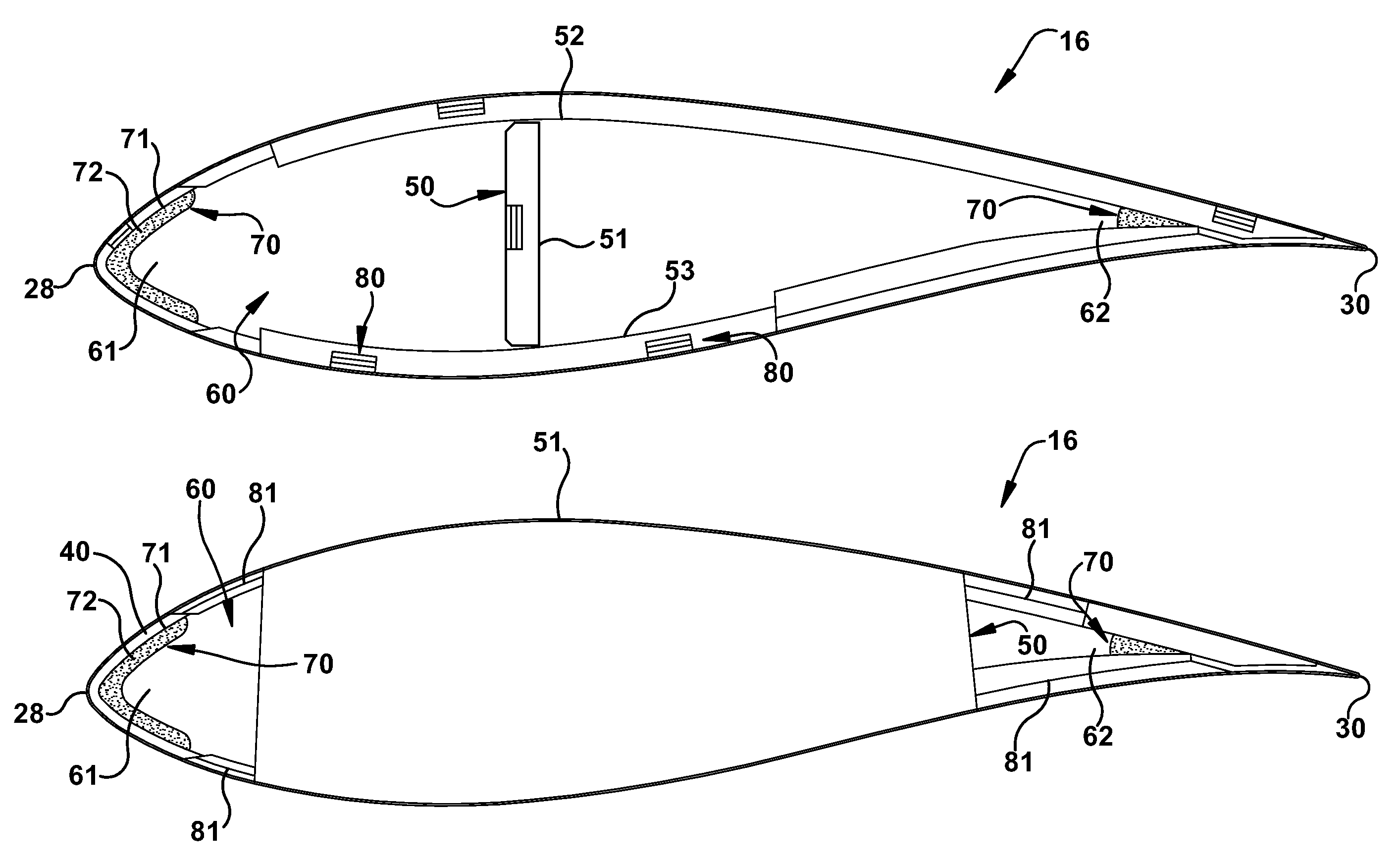
[0007]In another embodiment, a wind turbine rotor blade with a reduced radar cross section is provided. The wind turbine rotor blade includes a shell having a leading edge opposite a trailing edge and a structural support member that supports the shell and is disposed internal the wind turbine rotor blade between the leading edge and the trailing edge and extends for at least a portion of a rotor blade span length, wherein the structural support member comprises carbon fiber. The wind turbine rotor blade further includes a first resistive layer disposed about the shell between the structural support member and the leading edge blade to further provide the reduced radar cross section
[0008]In yet another embodiment, a wind turbine rotor blade with a reduced radar cross section is provided. The wind turbine rotor blade includes a shell having a leading edge opposite a trailing edge, a structural support member that supports the shell and is disposed internal the wind turbine rotor blade between the leading edge and the trailing edge and extends for at least a portion of a rotor blade span length, wherein the structural support member comprises carbon fiber. The wind turbine rotor blade further includes a first resistive layer disposed about the shell between the structural support member and the trailing edge to further provide the reduced radar cross section.

Problems solved by technology

However, some position-based restrictions may inhibit the feasibility of placing wind turbines and certain locations.
Placing wind turbines near such radar stations may result in consistent or occasional radar feedback due to the radar cross section of one or more components of the wind turbines and thereby impede the monitoring of space on the opposite side of such wind turbines.

Method used


Image

  • Wind turbine rotor blades with reduced radar cross sections
  • Wind turbine rotor blades with reduced radar cross sections
  • Wind turbine rotor blades with reduced radar cross sections

Examples


Embodiment Construction

[0017]One or more specific embodiments of the present invention will be described below. In an effort to provide a concise description of these embodiments, all features of an actual implementation may not be described in the specification. It should be appreciated that in the development of any such actual implementation, as in any engineering or design project, numerous implementation-specific decisions must be made to achieve the developers' specific goals, such as compliance with system-related and business-related constraints, which may vary from one implementation to another. Moreover, it should be appreciated that such a development effort might be complex and time consuming, but would nevertheless be a routine undertaking of design, fabrication, and manufacture for those of ordinary skill having the benefit of this disclosure.

[0018]When introducing elements of various embodiments of the present invention, the articles “a,”“an,”“the,” and “said” are intended to mean that ther...


PUM


Abstract

Wind turbine rotor blades with a reduced radar cross sections include a shell having a leading edge opposite a trailing edge, a structural support member that supports the shell and is disposed internal the wind turbine rotor blade between the leading edge and the trailing edge and extends for at least a portion of a rotor blade span length, wherein the structural support member comprises carbon fiber, one or more cavities internal the wind turbine rotor blade, and a lightweight broadband radar absorbing filler material disposed in at least one of the one or more cavities to provide the reduced radar cross section.

Description

CROSS REFERENCE TO RELATED APPLICATION[0001]This application is related to Ser. No. 13 / 348,589, filed concurrently herewith on Jan. 11, 2012, which is fully incorporated herein by reference and made a part hereof.BACKGROUND OF THE INVENTION[0002]The subject matter disclosed herein relates to wind turbines and, more specifically, to wind turbines and wind turbine rotor blades with reduced radar cross sections.[0003]Wind power can be considered one of the cleanest, most environmentally friendly energy sources presently available, and wind turbines have gained increased attention in this regard. A wind turbine can include a tower, generator, gearbox, nacelle, and one or more rotor blades comprising a composite material. The rotor blades capture kinetic energy from wind using known foil principles and transmit the kinetic energy through rotational energy to turn a shaft coupling the rotor blades to a gearbox, or if a gearbox is not used, directly to the generator. The generator then con...

Claims


Application Information

Patent Timeline
Patent Type & Authority Patents(United States)
IPC IPC(8): F03D1/06
CPCF03D1/0675F05B2260/99Y02E10/721Y02E10/726Y02E10/72
Inventor BAUCKE, RUSSELL CRAIGPRESCOTT, JOHN MATTHEWWALTERS, LESLY SUEHILDERBRAND, GLEN DAVID
Owner LM WIND POWER US TECH APS
Learn More