Liquid patch antenna

A patch antenna and liquid technology, applied in the field of antennas, can solve the problem of antenna stability to be improved, and achieve the effects of excellent concealment characteristics, reduced radar reflection cross section, and high radiation efficiency

Pending Publication Date: 2018-03-09
SOUTH CHINA UNIV OF TECH
View PDF5 Cites 4 Cited by
  • Summary
  • Abstract
  • Description
  • Claims
  • Application Information

AI Technical Summary

Problems solved by technology

In 2012, Tam D.W. used the fluidity of liquid to design a dynamic seawater monopole antenna. The water column sprayed by the water pump is used as the monopole radiation structure

Method used


Image

  • Liquid patch antenna
  • Liquid patch antenna
  • Liquid patch antenna

Examples


Embodiment Construction

[0026] The present invention will be further described below in conjunction with specific examples.

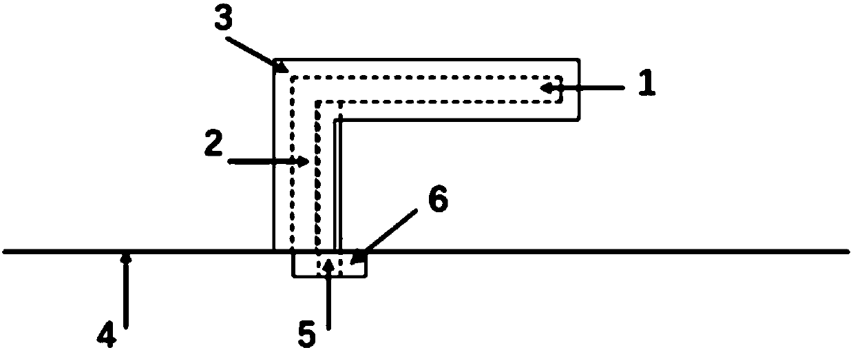
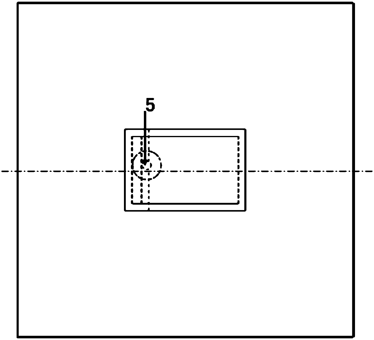
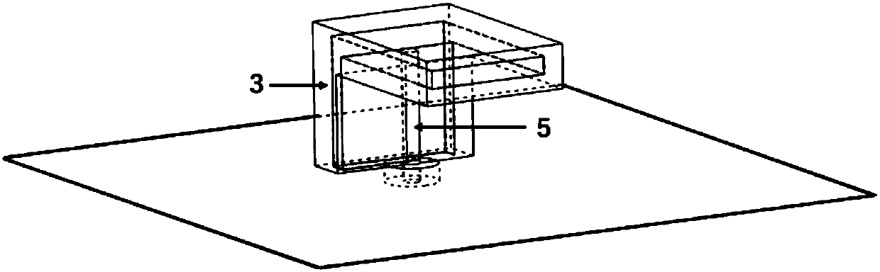
[0027] see figure 1 As shown, the liquid patch antenna provided in this embodiment includes a dielectric substrate 4 with a metal floor (not shown in the figure), an excitation port 6, a metal probe 5, and a non-metallic substrate with a built-in liquid (preferably pure water). Radiation patch 1, non-metallic short-circuit patch 2 with built-in liquid (preferably pure water) and container 3 made of resin glass, wherein, said non-metallic short-circuit patch 2 is vertically fixed on the metal floor, and one end thereof is connected to The metal floor is connected to form a ground short circuit, and the other end is connected to the non-metallic radiation patch 1 parallel to the metal floor. The non-metallic short-circuit patch 2 and the non-metallic radiation patch 1 form an inverted L structure, and both of them The same axis of symmetry, their internal liquids are connected,...


PUM


Abstract

The invention discloses a liquid patch antenna. The liquid patch antenna comprises a medium base plate which is provided with a metal floor, an exciting end port, a metal probe, a nonmetal radiation patch in which liquid is poured, and a nonmetal short circuit patch in which liquid is poured, wherein the nonmetal short circuit patch is vertically fixed to the metal floor; one end of the nonmetal short circuit patch is connected to the metal floor to form an earth short circuit, and the other end of the nonmetal short circuit patch is connected to the nonmetal radiation patch which is parallelto the metal floor; the nonmetal short circuit patch and the nonmetal radiation patch form an inverted L-shaped structure; liquid in the nonmetal short circuit patch is communicated with the liquid inthe nonmetal radiation patch; one end of the metal probe passes through the medium base plate and then extends into the nonmetal radiation patch, and the other end of the metal probe is equipped withthe exciting end port; and the metal probe is parallel with and close to the nonmetal short circuit patch without direct contact. The liquid patch antenna has the characteristics of being high in radiation efficiency, high in gain, high in impedance bandwidth and universal radiation, and the working frequency ranges from 2.26-3.24GHz.

Description

technical field [0001] The invention relates to the field of antennas, in particular to a liquid patch antenna. Background technique [0002] With the development of communication technology, the requirements for various performances of antennas in communication applications are getting higher and higher. People hope that the size of the antenna should be small, the radiation efficiency should be high, the gain should be high, the bandwidth should be wide, and the omniphase performance should be good. The traditional antenna structure is gradually difficult to meet these requirements, prompting researchers to continuously explore the application of new materials and technologies in antenna technology. Liquid antennas are an important research direction for the application of new materials in antenna technology. [0003] Traditional antennas, especially patch antennas, mainly use metal as the radiation structure, and the idea of ​​liquid antennas is to replace the solid metal...

Claims


Application Information

Patent Timeline
IPC IPC(8): H01Q1/36H01Q1/50H01Q1/48
CPCH01Q1/36H01Q1/48H01Q1/50Y02D30/70
Inventor 褚庆昕王磊
Owner SOUTH CHINA UNIV OF TECH
Why Eureka
Try Eureka