Polarizing plate, optical film and image display

A technology of polarizers and films, applied in optics, optical elements, polarizing elements, etc., can solve the problems of unsatisfactory durability, large dimensional changes, and dimensional changes, and achieve good dimensional stability, high durability, and good adhesion sexual effect

Active Publication Date: 2013-10-02
NITTO DENKO CORP
View PDF14 Cites 0 Cited by
  • Summary
  • Abstract
  • Description
  • Claims
  • Application Information

AI Technical Summary

Problems solved by technology

[0005] In addition, when using a water-based adhesive (so-called wet lamination), in order to improve the adhesiveness with the adhesive, unless the moisture content of the polarizer is relatively increased (usually the moisture content of the polarizer is about 30%), it is impossible to obtain Polarizers with good adhesion produced by water-based adhesives
However, the polarizing plate obtained in this way has problems such as large dimensional changes due to high temperature and high temperature and high humidity.
However, in the polarizing plate using the above-mentioned water-based adhesive, there is a problem that the size of the polarizing plate changes due to the heat of the backlight, and this becomes a speckle, and a part of the entire screen is seen as a black display that is regarded as white. So-called light leaks (spots) become conspicuous
However, in the above-mentioned polarizing plate, the durability under the above-mentioned severe environment cannot be satisfied.

Method used


Image

  • Polarizing plate, optical film and image display
  • Polarizing plate, optical film and image display
  • Polarizing plate, optical film and image display

Examples


Embodiment 1

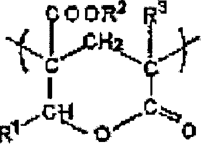
[0167] (Adhesive: curable component)

[0168] As an adhesive, N-acryloylmorpholine was used.

[0169] (production of polarizer)

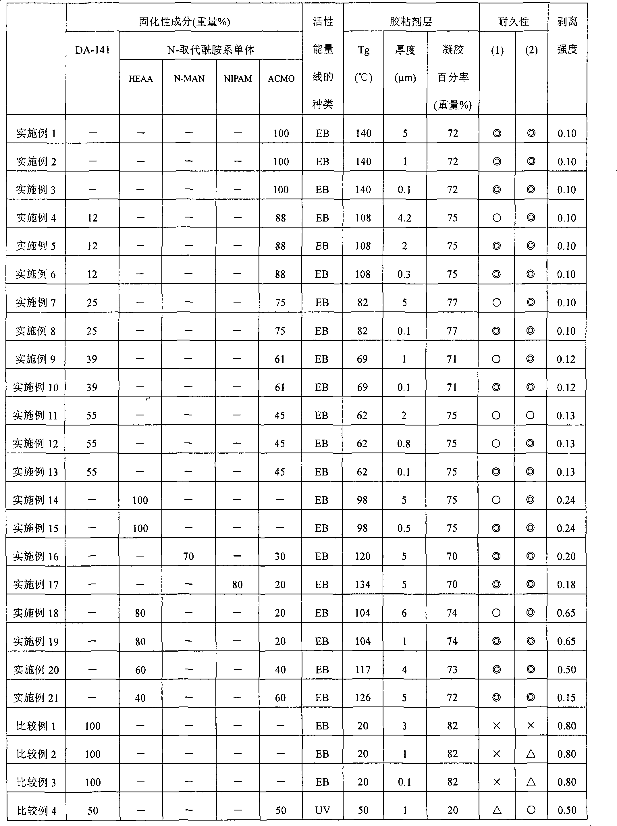
[0170] On one side of the above-mentioned transparent protective film, the above-mentioned adhesive was coated with a microgravure coating agent (gravure roll: #180, rotation speed 140% / line speed) to a thickness of 5 μm to obtain an adhesive-attached transparent protective film. Next, the above-mentioned transparent protective film with an adhesive was bonded to both surfaces of the above-mentioned polarizer using a roll mill. Electron beams were irradiated from the bonded transparent protective film side (both sides) to obtain a polarizing plate having a transparent protective film on both sides of the polarizer. The linear velocity is 20m / min, the accelerating voltage is 250kV, and the irradiation dose is 20kGy. The Tg was 140°C, and the gel percentage was 72% by weight.

Embodiment 2~21、 comparative example 1~11

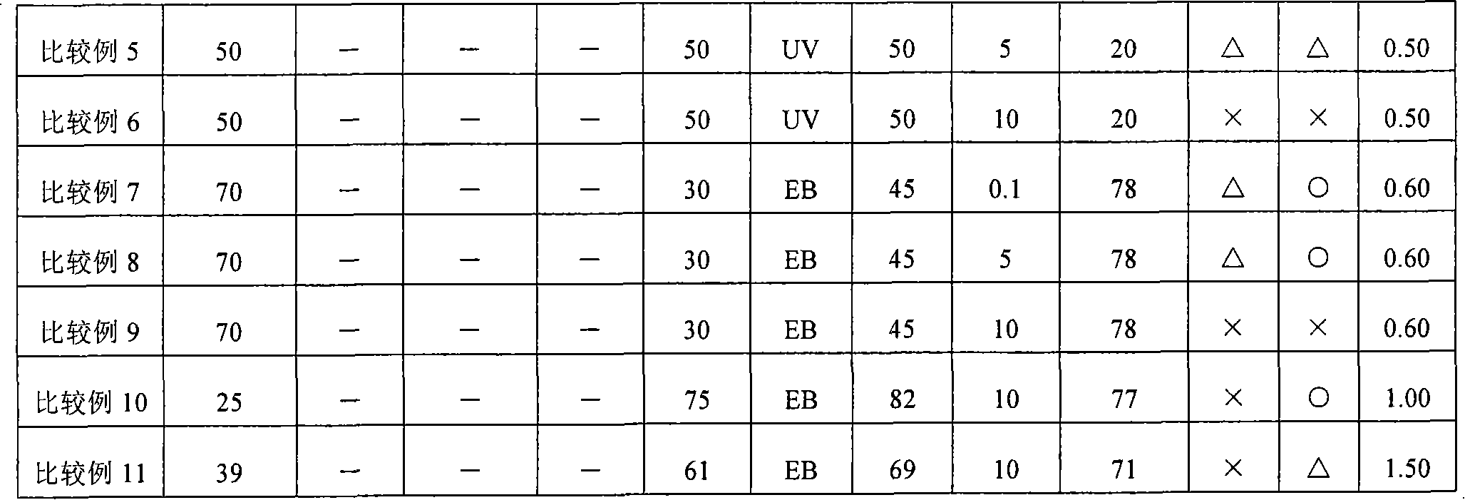
[0172] In Example 1, when the kind of curable component was used together, except having changed the ratio and the thickness of the adhesive layer as shown in Table 1, it carried out similarly to Example 1, and obtained the polarizing plate. In addition, in Comparative Examples 4-6, 3 weight part of polymerization initiators were added and used with respect to 100 weight part of curable components. In addition, the gravure roll changes into a mirror surface at 0.1μm, 0.3μm, and 0.5μm, #300 at 0.8μm and 1μm, #280 at 2μm, #250 at 3μm, and #250 at 4μm according to the thickness of the adhesive layer. and 4.2μm change to #220, change to #180 at 5μm and 6μm, change to #120 at 10μm. Table 1 shows the Tg and gel percentage of the adhesive layer of each example.


PUM

PropertyMeasurementUnit
glass transition temperatureaaaaaaaaaa
thicknessaaaaaaaaaa
glass transition temperatureaaaaaaaaaa

Abstract

A polarizing plate, an optical film, and an image display are provided to improve durability and productivity without a heating process by using an electron beam curing adhesive. A polarizing plate includes a polarizer, an adhesive layer, and a transparent protective film. The transparent protective film is formed on at least one surface of the polarizer while interposing the adhesive layer therebetween. The adhesive layer is made of an active energy ray curing adhesive containing at least one curing component. A glass transition temperature of the adhesive layer is more than 60°C. A thickness of the adhesive layer is 0.01 to 7mum. A gel fraction of the adhesive layer is more than 50wt%.

Description

technical field [0001] The present invention relates to a polarizer. The polarizing plate can be used alone or as an optical film laminated with a polarizing plate to form image display devices such as liquid crystal display (LCD), organic EL display, CRT, and PDP. Background technique [0002] The market for liquid crystal display devices is rapidly expanding in watches, mobile phones, PDPs, notebook computers, monitors for personal computers, DVD players, TVs, and the like. A liquid crystal display device is a device for visualizing a state of polarized light caused by conversion of liquid crystals, and a polarizer is used in view of its display principle. Especially in applications such as TV, high brightness, high contrast, and wide viewing angle are increasingly required. Even for polarizers, high transmittance, high polarization, and high color reproducibility are increasingly required. [0003] As a polarizer, an iodine-based polarizer having a structure in which io...

Claims


Application Information

Patent Timeline
Patent Type & Authority Patents(China)
IPC IPC(8): G02B5/30G02B1/10G02F1/1335C09J4/00
CPCB29D11/00788B32B7/12G02B5/3041G02F1/133528
Inventor 赤利玲子池田哲朗中野勇树八重樫将宽铃木畅佐竹正之石桥邦昭
Owner NITTO DENKO CORP
Why Eureka
Try Eureka