Silicon rubber sleeve expansion method and device

A silicone rubber sleeve and expansion device technology, which is applied to tubular objects, household appliances, and other household appliances, can solve problems affecting the contact of cold-shrinkable terminal parts, cracking of silicone rubber tubes, and cracking of cold-shrinkable sleeves. Easy to process, easy to operate, clean expansion operation

Inactive Publication Date: 2009-03-18
CHANGCHUN UNIV OF SCI & TECH
View PDF0 Cites 9 Cited by
  • Summary
  • Abstract
  • Description
  • Claims
  • Application Information

AI Technical Summary

Problems solved by technology

The disadvantage is that the force of the cylinder is very large, it is not suitable for long and thin silicone pipe fittings, only suitable for short and thick pipe fittings, and it needs to apply a large amount of silicone oil grease
And these lubricants will be absorbed by the silicone rubber tube, which will easily cause the cracking of the silicone rubber tube
[0007] A large amount of lubricating grease will form an oil film on the conductive part material, which will affect the contact between the stress cone in the cold shrink terminal and the outer semiconducting layer of the cable, and will easily cause the cold shrink sleeve to crack during storage.

Method used


Image

  • Silicon rubber sleeve expansion method and device

Examples


Embodiment 1

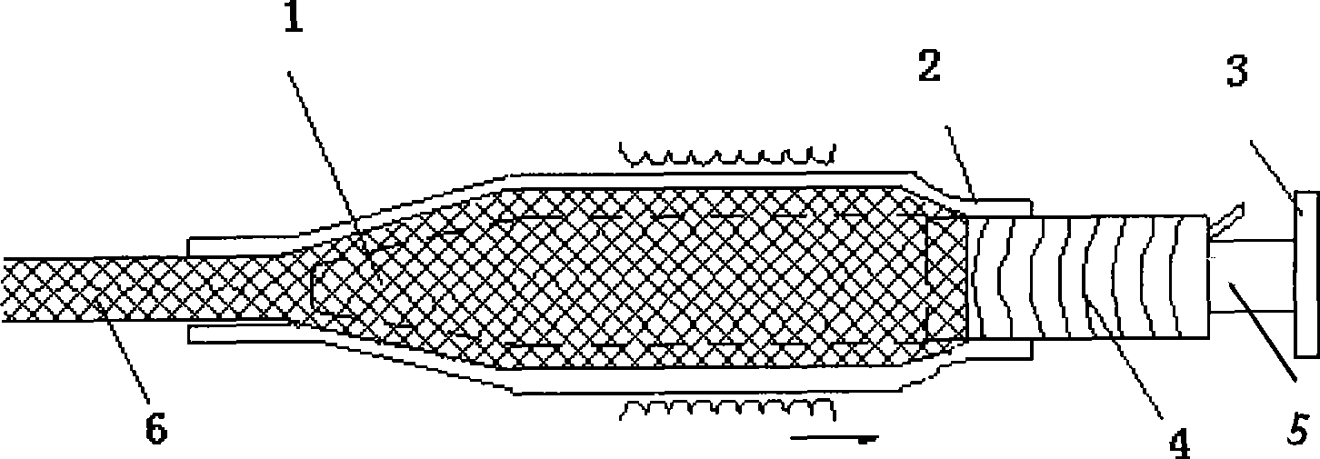
[0022] Such as figure 1 As shown, the silicone rubber sleeve expansion device is characterized in that: there is a cavity at the tail end of the expansion head, the spiral support tube is inserted into the cavity, and there is a push rod, which can hold the spiral support bar to wrap the tube, The ejector rod and the ejector rod support are plug-in connections, and there is a nylon mesh sleeve between the silicone rubber tube and the steel rod as a spacer; the specific method is as follows:

[0023] 1. Fix the ejector rod support of the metal structure on the wall or other side of the base that can withstand the thrust within 100KG in the horizontal direction;

[0024] 2. Adjust the specifications of the iron expansion head and the spiral support tube to correspond to the size to be expanded, and insert the spiral support tube into the tail cavity of the iron expansion head;

[0025] 3. Insert the ejector rod together with the spiral tube into the ejector rod support. After c...

Embodiment 2

[0031] 1. Fix the ejector rod support of the metal structure on the wall or other side of the base that can withstand the thrust within 100KG in the horizontal direction;

[0032] 2. Adjust the specifications of the steel expansion head and the spiral support tube to correspond to the size to be expanded, and insert the spiral support tube into the tail cavity of the steel expansion head;

[0033] 3. Insert the ejector rod together with the spiral tube into the ejector rod support. After confirming that the connection with the ejector rod support is firm and the position is appropriate, retreat the spiral tube into the tail cavity of the ejector rod to expose the spiral tube at a distance of 45mm;

[0034] 4. Select a propylene rubber sleeve and a strong PE wire mesh sleeve with the corresponding size, feed the nylon mesh sleeve into the propylene rubber tube, and expose a strong PE wire mesh sleeve 15mm toward the end of the ejector rod support;

[0035] 5. Put one end of the...

Embodiment 3

[0039] 1. Fix the ejector rod support of the metal structure on the wall or other side of the base that can withstand the thrust within 100KG in the horizontal direction;

[0040] 2. Adjust the specifications of the aluminum expansion head and the spiral support tube to correspond to the size to be expanded, and insert the spiral support tube into the tail cavity of the aluminum expansion head;

[0041] 3. Insert the ejector rod together with the spiral tube into the ejector rod support. After confirming that the connection with the ejector rod support is firm and the position is appropriate, retreat the spiral tube into the tail cavity of the ejector rod to expose the spiral tube at a distance of 50mm;

[0042] 4. Select a natural rubber sleeve and a strong PET wire mesh sleeve with the corresponding size, feed the PET wire mesh sleeve into the natural rubber tube, and expose the PET wire mesh sleeve 20mm toward the end of the ejector rod support;

[0043] 5. Put one end of the...


PUM


Abstract

The invention relates to a silastic bushing expansion method and a device thereof. The invention is characterized in that the tail end of an expansion head is provided with an empty cavity; a spiral supporting pipe is inserted into the empty cavity and is provided with a top rod; the top rod can support a spiral supporting strip winding pipe; the top rod and a support saddle thereof are connected in an inserting way; a net sleeve is arranged between a silastic tube and a steel stick as a spacer. The air clearance formed after a nylon sleeve is sheathed on the expansion head can reduce much resistance in the silastic tube and hauls a silastic piece on a plastic spiral pipe by proper force. The silastic bushing expansion method and the device thereof have the advantages of clean expansion, non-large mechanical power and being suitable for the expansion of a short and thick pipe.

Description

technical field [0001] The invention relates to a silicone rubber sleeve expansion method and device, and relates to the technical field of expansion of rubber sleeves in the manufacturing process of cold shrinkable sleeves. Background technique [0002] Silicone rubber cold-shrinkable material is a new type of functional polymer material. Its manufacturing principle is to use the characteristics of automatic reset after rubber stretching: first prepare silicone rubber tubes or parts, expand them and embed them in supports, and support them when they are applied. When the object is removed, the rubber tube will automatically reset and shrink on the covered object. Compared with the heating and shrinking process of heat-shrinkable materials, the automatic reset of silicone rubber tubes is called "cold shrinkage" because there is no heating means in the shrinking process. This type of material is called "cold shrinkable materials", also referred to as "cold shrinkable material...

Claims


Application Information

Patent Timeline
Patent Type & Authority Applications(China)
IPC IPC(8): B29C61/00B29K19/00B29L23/00
Inventor 苗润忠
Owner CHANGCHUN UNIV OF SCI & TECH
Why Eureka
Try Eureka