Microwave de-icing apparatus and de-icing method for electric power facilities

A technology of power facilities and microwaves, applied in the installation of cables, electromagnetic wave systems, electrical components, etc., can solve the problems of inconvenient operation, high energy consumption and low efficiency in actual engineering

Inactive Publication Date: 2011-04-20
INST OF ELECTRICAL ENG CHINESE ACAD OF SCI +1
View PDF0 Cites 0 Cited by
  • Summary
  • Abstract
  • Description
  • Claims
  • Application Information

AI Technical Summary

Problems solved by technology

[0006] The purpose of the present invention is to overcome the shortcomings of existing deicing methods such as high energy consumption, poor safety, low efficiency, high labor intensity, harsh working environment, and inconvenient actual engineering operations, and propose a microwave deicing device and deicing method. The invention is suitable for deicing of power facilities in substations

Method used


Image

  • Microwave de-icing apparatus and de-icing method for electric power facilities
  • Microwave de-icing apparatus and de-icing method for electric power facilities
  • Microwave de-icing apparatus and de-icing method for electric power facilities

Examples


Embodiment Construction

[0016] The present invention will be further described below in conjunction with the accompanying drawings and specific embodiments.

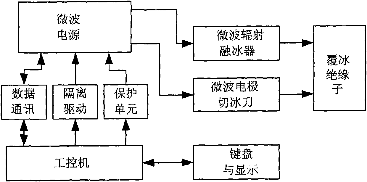
[0017] Such as figure 1 The shown deicing system of the present invention is mainly composed of a microwave power supply, a microwave radiation ice melting device, and a microwave electrode ice cutter. The deicing method adopts microwave radiation melting ice and microwave electrode ice cutting. Through the organic combination and mutual cooperation of the two methods, it can deal with different ice coating states and achieve the purpose of deicing the insulators of power facilities.

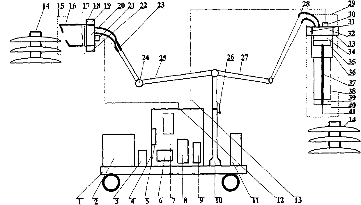
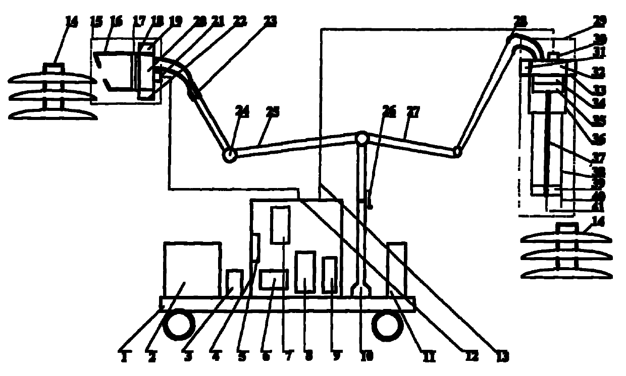
[0018] The device of the present invention mainly includes a microwave power supply 4 , a microwave radiation ice melting device 15 , a microwave electrode ice cutter 29 and an adjustable support 10 . Wherein the microwave power supply 4 is fixed on the mobile device 1, and the microwave radiation ice melting device 15 and the microwave electrode ice cutter 29 a...


PUM


Abstract

The invention relates to a microwave deicing device for an electric power facility, in particular to a microwave deicing device for an electric power facility and a deicing method thereof. The microwave deicing device mainly comprises a mobile device, a microwave-radiation ice-melting device and a microwave electrode ice-cutting knife. The deicing method for the device adopts a microwave-radiation ice-melting mode and a microwave electrode ice-cutting mode, the different ice-covered states can be handled through the organic combination and the mutual matching of the two models, and the deicing is performed to the ice-covered insulator for the electric power facility.

Description

technical field [0001] The invention relates to a deicing device and a deicing method, in particular to a deicing device and a method for substation power facilities. Background technique [0002] With the significant increase in energy demand, the transmission power of transmission lines is also increasing, which puts forward higher requirements for the transmission voltage level. At present, my country has been at the forefront of the world in the application of ultra-high voltage and ultra-high voltage transmission. However, in many areas of my country, power transmission and transformation systems are covered with ice and snow, which has been threatening the safety of the power grid for many years. [0003] In 2005, due to the impact of ice and snow disasters in Central China Power Grid, 500 kV lines tripped many times, and many high-voltage transmission lines collapsed. , many 500 kV lines and substations in the North China Power Grid were covered with ice due to rain ...

Claims


Application Information

Patent Timeline
Patent Type & Authority Patents(China)
IPC IPC(8): H02G7/16H02J17/00H01J25/50
Inventor 夏慧刘国强李艳红李士强吴石增
Owner INST OF ELECTRICAL ENG CHINESE ACAD OF SCI
Why Eureka
Try Eureka