Closed-loop optic fiber gyroscope light path structure with low polarization error

A fiber optic gyro and low polarization technology, which is applied in the field of optical path structure of closed-loop fiber optic gyroscope, can solve problems such as how to use polarizer and polarizer requirements without specifying it, so as to improve optical path performance, avoid fusion angle error, and reduce polarization error Effect

Active Publication Date: 2009-07-15
BEIJING AEROSPACE TIMES OPTICAL ELECTRONICS TECH
View PDF0 Cites 17 Cited by
  • Summary
  • Abstract
  • Description
  • Claims
  • Application Information

AI Technical Summary

Problems solved by technology

For this reason, "Fiber optic gyroscope" published in 1993 mentioned that adding a polarizer in front of the detector can further suppress the intensity-type polarization error, but the article did not detail how to use the polarizer and the requirements for the polarizer
In addition, there is no other public literature report mentioning how to further suppress the polarization error

Method used


Image

  • Closed-loop optic fiber gyroscope light path structure with low polarization error
  • Closed-loop optic fiber gyroscope light path structure with low polarization error
  • Closed-loop optic fiber gyroscope light path structure with low polarization error

Examples


Embodiment Construction

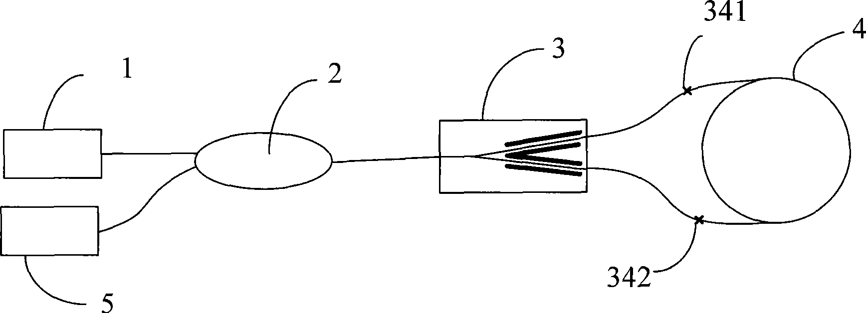
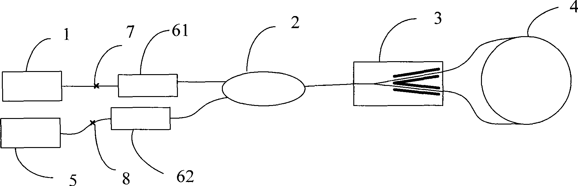
[0026] Such as figure 2 Shown is the structure of the fiber optic gyroscope optical path of the present invention, including a light source 1, a fiber coupler 2, a Y waveguide integrated optical device 3, a polarization-maintaining fiber coil 4 and a detector 5, and the light emitted by the light source 1 passes through the fiber coupler 2, The Y-waveguide integrated optical device 3 reaches the polarization-maintaining optical fiber coil 4, then reaches the Y-waveguide integrated optical device 3 in the reverse direction, and then interferes, and finally passes through the fiber coupler 2 and then reaches the detector 5, the Y-waveguide integrated optical device 3 and the polarization-maintaining optical fiber The coils 4 are directly coupled, and in order to reduce polarization errors, a polarizer 61 is arranged between the light source 1 and the fiber coupler 2 , and a polarizer 62 is arranged between the detector 5 and the fiber coupler 2 .

[0027] After adding the polar...


PUM


Abstract

The invention relates to a closed loop optical fiber gyro light path structure with low polarization error, which comprises a light source, a optical fiber coupler, a gamma waveguide integrated optical device, a polarization maintaining optical fiber loop and a detector; the light from the light source passes through the optical fiber coupler, the gamma waveguide integrated optical device and reaches the polarization maintaining optical fiber loop, then goes reverse direction to the gamma waveguide integrated optical device to interfere, passes through the optical fiber coupler and finally reach the detector. For reducing polarization error, polarizers are connected both between the light source and the optical coupler and between the detector and the optical coupler. The light path structure of the invention is characterized in low polarization error, can reduce the amplitude type polarization error to 1 / 5 of the original, and intensity type polarization to 1 / 31 of the original, and improves the light path polarization performance considerably.

Description

technical field [0001] The invention relates to an optical path structure, in particular to an optical path structure of a closed-loop fiber optic gyroscope. Background technique [0002] Fiber optic gyroscope is a new type of inertial device. It has no moving parts in its structure, and has the advantages of small size, low power consumption, fast start-up, large dynamic range, wide accuracy coverage, long life, high reliability, and low batch cost. There are two schemes of open-loop and closed-loop fiber optic gyroscopes. The closed-loop fiber optic gyroscope is more widely used because of its small nonlinear scale factor and high precision. The typical optical path of the closed-loop fiber optic gyroscope is as follows: figure 1 As shown in the figure, 1 is the light source, 2 is the fiber coupler, 3 is the Y-waveguide integrated optical device, 4 is the polarization-maintaining fiber coil, and 5 is the detector. The aforementioned five optoelectronic devices are all dev...

Claims


Application Information

Patent Timeline
Patent Type & Authority Applications(China)
IPC IPC(8): G01C19/72
Inventor 王巍王学锋杨清生高峰李晶丁东发
Owner BEIJING AEROSPACE TIMES OPTICAL ELECTRONICS TECH
Why Eureka
Try Eureka