Multi-stage pulse sequence control method of pseudo-continuous working mode and apparatus thereof

A pseudo-continuous operation and mode switching technology, which is applied in the field of multi-level pulse sequence control of pseudo-continuous operation mode switching power supply and its devices, can solve the problems of large fluctuation of the output voltage of the converter and is not suitable for high-power occasions, and achieves widening Application-wide effects

Inactive Publication Date: 2009-08-12
SOUTHWEST JIAOTONG UNIV
View PDF0 Cites 21 Cited by
  • Summary
  • Abstract
  • Description
  • Claims
  • Application Information

AI Technical Summary

Problems solved by technology

Its shortcomings are: it can only be used to control switching converters working in the inductor current discontinuous mode (DCM), and the working rang

Method used


Image

  • Multi-stage pulse sequence control method of pseudo-continuous working mode and apparatus thereof
  • Multi-stage pulse sequence control method of pseudo-continuous working mode and apparatus thereof
  • Multi-stage pulse sequence control method of pseudo-continuous working mode and apparatus thereof

Examples


Embodiment 1

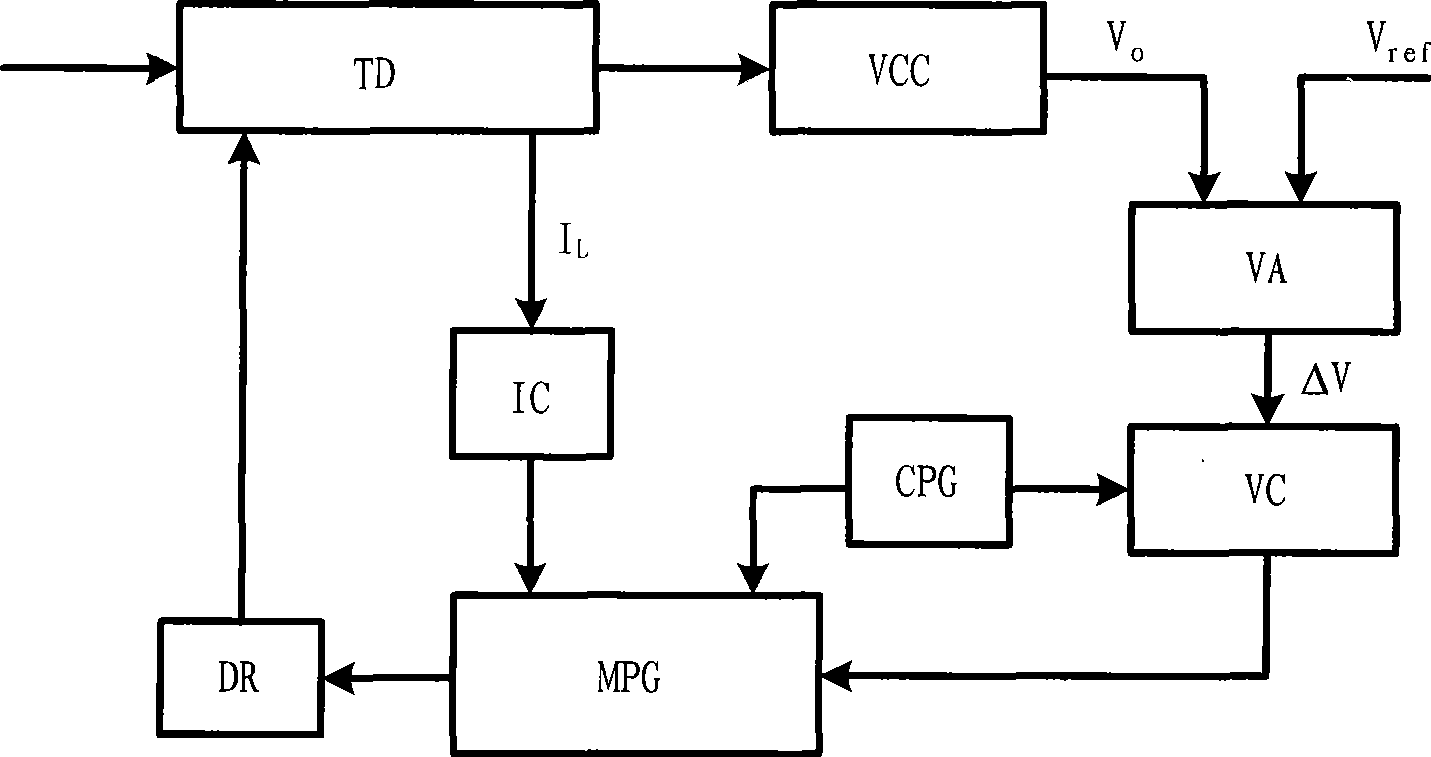
[0045] figure 1 It is shown that a specific embodiment of the present invention is a control method of a switching power supply, and its specific method is:

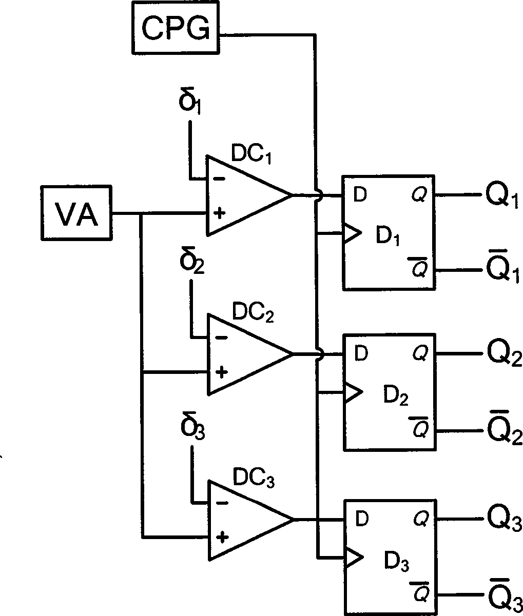
[0046] The voltage detection circuit VCC detects the output voltage V of the converter TD 0 , the error amplifier VA uses the output reference voltage V at the beginning of each switching cycle ref with the output voltage V 0 The error voltage value ΔV is generated by comparison; the error interval judger VC compares the error voltage value ΔV with the set N=3 output voltage error interval value δ n , n=1, 2, 3, compare, and output corresponding control pulse selection signals to the multi-level pulse generator MPG according to the comparison results, the comparison and selection rules are: when ΔV>δ 1 When , the output signal of the error interval judge VC makes the multi-level pulse generator MPG generate a control pulse P 11 and P 12 ; when δ 1 ≥ΔV>δ 2 When , the output signal makes the multi-stage pulse genera...

Embodiment 2

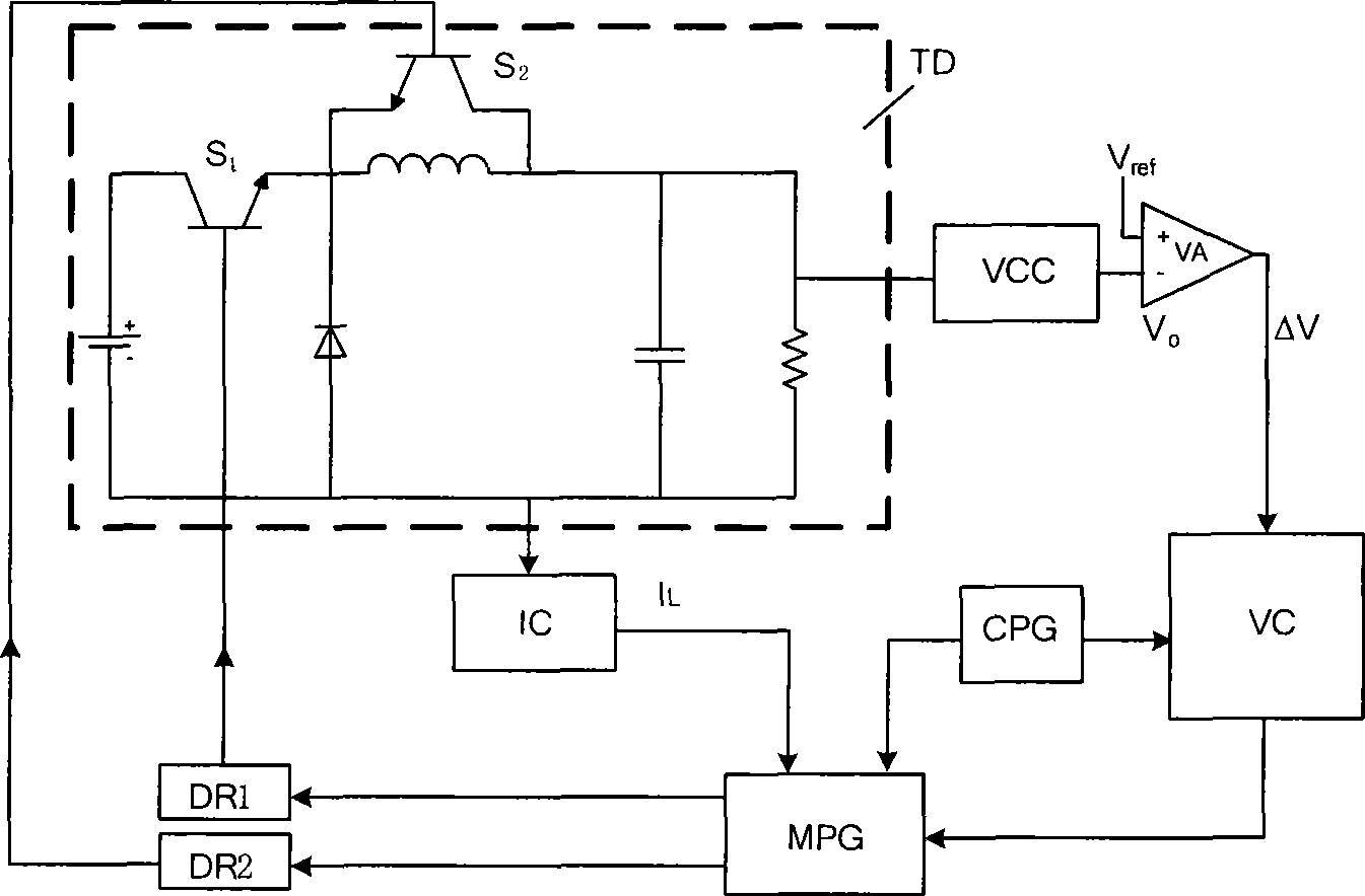
[0063] Figure 8 It shows that this example is basically the same as Embodiment 1, the difference is that: the number N of error interval values ​​of the set output voltage is 4, and δ n , n=1, 2, 3, 4, the corresponding control pulse P n1 is five, namely P 11 ,P 21 ,P 31 ,P 41 ,P 51 . Multi-stage pulse generator MPG generates control pulse P n , the method of n=1, 2, 3, 4, 5 is: the multistage pulse generator (MPG) outputs P at the beginning of each switching cycle n1 is high level, P n2 is low, the inductor current I in the converter (TD) L start to rise;P n1 Continuous high level fixed time D n After T, it becomes low level; the current I L then begins to drop, when I L drops until the current valley I V , the control pulse P n2 From low level to high level, the diode is turned off, and the inductor current passes through the switch tube S 2 freewheel until the end of the switching cycle.

[0064] The converter TD of the switching power supply controlled in...

Embodiment 3

[0066] Figure 9 It shows that this example is basically the same as the first example, the difference is: the number N of error interval values ​​of the set output voltage is 5, and δ n , n=1, 2, 3, 4, 5, the corresponding control pulse P n1 is six, namely P 11 ,P 21 ,P 31 ,P 41 ,P 51 ,P 61 . Multi-stage pulse generator MPG generates control pulse P n , the method of n=1, 2, 3, 4, 5, 6 is: the multistage pulse generator (MPG) outputs P at the beginning of each switching cycle n1 is high level, P n2 is low, the voltage V on the equivalent series resistance (ESR) of the capacitor in the converter (TD) ESR Start to rise; the voltage detection circuit (VCC') detects the voltage V synchronously ESR , the multistage pulse generator (MPG) takes the voltage signal V ESR with the period of the control pulse P n1 , n=1, 2,...N+1, the corresponding peak voltage V n , n=1, 2,...N+1, for comparison, when the voltage V ESR rises to the peak value corresponding to V n , the ...


PUM


Abstract

The invention relates to a method for the multi-pulse sequence control of a switch power supply working in a pseudo continuous mode, which comprises the following steps that: a voltage detection circuit (VCC) detects the output voltage V0 of a convertor and transmits the output voltage to an error amplifier (VA); at the beginning time of each switch cycle, the error amplifier (VA) compares an output reference voltage Vref with the output voltage V0 to generate an error voltage value delta V; and an error burst judger (VC) compares the error voltage value delta V with a preset error burst value deltan ( n is an integer from 1 to N) of N(N is more than or equal to 1) output voltages, and outputs a control pulse selection signal according to the result of the comparison to make a multi-pulse generator (MPG) generate control pulses Pn1 and Pn2 with different duty cycles to control the switching tubes S1 and S2 of the a converter TD respectively, wherein the n is an integer from 1 to N+1. The method can realize the multi-pulse sequence control of the switch power supply working in a pseudo continuous mode. The converter adopting the control method has current critical condition limitation-free output power, small output voltage ripples, excellent dynamic response and high disturbance resistance, and is applicable to convertors of various topological structures.

Description

technical field [0001] The invention relates to a control method and device for a switching power supply. Background technique [0002] In recent years, power electronics technology has developed rapidly, and power supply technology, which is an important part of the field of power electronics, has become a hot spot in application and research. With the advancement of power electronic device manufacturing technology and converter technology, switching power supply has established its mainstream position in DC-DC conversion. Computers, communication equipment, electronic testing equipment, control equipment, etc. are widely used switching power supply as a power supply device. The switching power supply is mainly composed of two parts, the converter and the controller. Converters are also called power circuits, mainly including switching devices, transformer devices and rectification and filtering circuits; converters have Buck, Boost, forward, flyback and other topological...

Claims


Application Information

Patent Timeline
IPC IPC(8): H02M3/156
Inventor 许建平秦明王金平周国华吴松荣
Owner SOUTHWEST JIAOTONG UNIV
Why Eureka
Try Eureka