Inrush flow-free switching device and control method thereof

A control method and inrush current technology, applied in the electrical field, can solve the problems of short conduction time of thyristors, and achieve the effects of short conduction time, high cost performance and long electrical life.

Active Publication Date: 2017-01-04
GUANGZHOU JINSHI ELECTRONICS
View PDF5 Cites 5 Cited by
  • Summary
  • Abstract
  • Description
  • Claims
  • Application Information

AI Technical Summary

Problems solved by technology

[0006] The purpose of the present invention is to provide a non-surge switching device with short thyristor conduction time, strong overload capacity, high cost performance, long electric

Method used


Image

  • Inrush flow-free switching device and control method thereof

Examples


Embodiment Construction

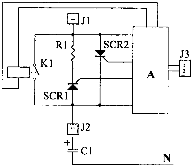
[0023] Embodiment 1 of the non-surge switching device of the present invention, such as figure 1 Shown:

[0024] A switching device without inrush current, comprising a mechanical switch K1 (an electromagnetic switch, the control end of which is the control coil of the electromagnetic switch, or other mechanical switches), also includes a first one-way thyristor SCR1, a second one-way thyristor The thyristor SCR2, the control unit (A), the current limiting element R1 (a current limiting resistor), the first unidirectional thyristor SCR1 and the current limiting element R1 are connected in series to form a series circuit, and the series circuit is connected in parallel with the second unidirectional thyristor SCR2, mechanically Both ends of the main circuit of the switch K1 are connected in parallel with the second one-way thyristor SCR2, the control unit (A) is connected with the control terminal of the mechanical switch K1, the control unit (A) is connected with the first one...


PUM


Abstract

The invention discloses an inrush flow-free switching device and a control method thereof, and belongs to the electric field, and discloses the inrush flow-free switching device especially suitable for switching of capacitors and other capacitive loads, and the control method thereof. The inrush flow-free switching device comprises a mechanical switch, a first unidirectional thyristor, a second unidirectional thyristor, a control unit, and a limiting element. The first unidirectional thyristor is serially connected with the limiting element to form a serial connection circuit. The serial connection circuit is parallely connected with the second unidirectional thyristor, and the two ends of the main circuit of the mechanical switch are parallely connected with the second unidirectional thyristor. The control unit is connected with the control end of the mechanical switch, and is connected with the first unidirectional thyristor and the second unidirectional thyristor. The motion time parameters of the mechanical switch are pre-stored in the control unit. The inrush flow-free switching device has advantages of short conduction time of thyristors, strong overload capability, high cost performance, long electric service lifetime of mechanical switch, and high reliability.

Description

technical field [0001] The invention relates to a non-inrush switching device and a control method thereof, belonging to the electrical field, in particular to a non-inrush switching device suitable for switching capacitive loads such as capacitors and a control method thereof. Background technique [0002] At present, in electrical control systems, non-inrush switching devices such as composite switches are widely used to control power capacitors and other loads on and off. It uses two unidirectional thyristors connected in reverse parallel and then connected with mechanical switches (magnetic latching relays and other electromagnetic switches) ) in parallel, during the connection process, the control unit first controls two unidirectional thyristors to conduct at zero crossing before the mechanical switch is closed, and then controls the mechanical switch to close. The existing composite switch has the following disadvantages: [0003] 1. Due to the capacitive load, it is...

Claims


Application Information

Patent Timeline
IPC IPC(8): H02J3/18
CPCH02J3/18Y02E40/30
Inventor 郭桥石
Owner GUANGZHOU JINSHI ELECTRONICS
Why Eureka
Try Eureka