Fast set low-power bias unit and method for single-end circuit

A technology of circuit and bias circuit, which is applied in the parts of amplifying devices, electrical components, low-noise amplifiers, etc., can solve the problems of slow turn-on time, increased cost, and poor RF performance, and achieve short turn-on time, Effect of eliminating up-conversion noise

Inactive Publication Date: 2002-07-10
TEXAS INSTR INC
View PDF0 Cites 7 Cited by
  • Summary
  • Abstract
  • Description
  • Claims
  • Application Information

AI Technical Summary

Problems solved by technology

As a result, when the amplifier is powered on, it takes a long time to establish its steady state, usually on the order of hundreds of milliseconds, which may not be acceptable in the overall system
Third, parasitics introduced by large external components can degrade RF performance
However, there are several practical problems with this implementation as described above, namely increased cost due to additional external components, slow turn-on time, degraded RF performance due to additional parasitics of external tank circuit components

Method used


Image

  • Fast set low-power bias unit and method for single-end circuit
  • Fast set low-power bias unit and method for single-end circuit
  • Fast set low-power bias unit and method for single-end circuit

Examples


Embodiment Construction

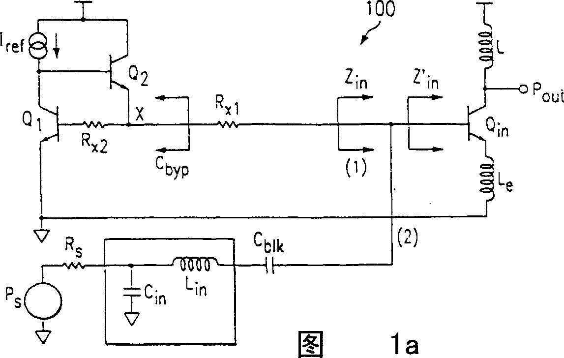
[0025] The proposed biasing device 300 and technique, as image 3 shown, can be implemented in a wide variety of single-ended circuits. A single-ended circuit such as an LNA (300) according to the present invention includes an input power matching circuit (310) and an output transistor (Q in ) of a bias circuit (305). Regenerative inductance (L e ) and load impedance (L o ) are coupled to the output transistors (Q i n) emitter and collector.

[0026] The bias circuit (305) is configured to cancel the output transistor (Q in ) base shot noise. The biasing circuit (305) according to the present invention also eliminates the biasing resistor (R x1 ) noise. Specifically, the bias circuit (305) includes a current reference source (I ref ) and emitter follower circuit (315), both connected to the current mirror circuit (Q 1 , Q 2 , R x2 ), the mirror circuit is connected to the bias resistor (R x1 ). The bias circuit (305) can be implemented in a wide variety of single...


PUM


Abstract

A single-ended circuit, such as an LNA (300), in accordance with the present invention includes an input power matching circuit (310) and a bias circuit (305) connected to an output transistor (Qin) which provides the amplification. A degeneration inductance (Le) and load impedance (Lo) couple to the emitter and collector of the output transistor (Qin), respectively. The bias circuit (305) is configured to eliminate base shot-noise of the mirror transistor (Q1) which generates the amplification. The bias circuit (305) in accordance with the present invention also eliminates the noise of the bias resistor (Rx1) that is included within the bias circuit (305). Specifically, the bias circuit (305) includes a current reference source (Iref) and an emitter follower circuit (315) connected to a current mirror circuit (Q1, Q2, Rx2) that connects to a bias resistor(Rx1). This bias circuit (305) can be implemented in a wide-class of single-ended circuits.

Description

technical field [0001] The present invention relates to semiconductor devices, and more particularly to a fast-setting low-power bias circuit for single-ended circuits. Background technique [0002] A radio frequency (RF) receiver includes a preamplifier that boosts the level of an incoming signal prior to frequency conversion processing. The presence of intermodulation products by greatly interfering with the signal compromises the ability of the receiver to handle very weak signals. This is what is commonly referred to as desensitization. Third-order intermodulation occurs when two interfering signals of different frequencies are combined in an amplifier with third-order nonlinearity, producing an intermodulation product close to the desired signal. [0003] Desensitization can also occur in the presence of a single large interfering signal (i.e. blocker or electrical jammer). The reduction in sensitivity occurs through two separate mechanisms. F...

Claims


Application Information

Patent Timeline
Patent Type & Authority Applications(China)
IPC IPC(8): H03F1/26H03F1/30
CPCH03F2200/294H03F1/302H03F2200/372
Inventor R·加尔普里G·西纳
Owner TEXAS INSTR INC
Why Eureka
Try Eureka