Switching type power convertor and its synchronous rectifier control method

A technology of synchronous rectifiers and power converters, which is applied in the direction of electrical components, circuit devices, AC network circuits, etc., and can solve problems such as high cost, large volume, and large loss

Inactive Publication Date: 2006-01-18
DELTA ELECTRONICS INC
View PDF1 Cites 6 Cited by
  • Summary
  • Abstract
  • Description
  • Claims
  • Application Information

AI Technical Summary

Problems solved by technology

The current of the synchronous rectifier on the secondary side of the power transformer can be detected by direct detection and indirect detection; the indirect detection method is to detect the current signal of the primary side of the transformer, then subtract the magnetization current of the primary side of the transformer, and obtain the secondary The current of the secondary side synchronous rectifier, the disadvantage of the indirect method is that the detection accuracy is not very high
In addition, direct detection is to use Hall sensor (Hall sensor), current transformer (current transformer), or sensing resistor (sensing resistor) to directly obtain the current information of the synchronous rectifier, but these detection methods will encounter problems such as Difficulties such as high cost, large volume, and large loss are relatively rare in actual product applications

Method used


Image

  • Switching type power convertor and its synchronous rectifier control method
  • Switching type power convertor and its synchronous rectifier control method
  • Switching type power convertor and its synchronous rectifier control method

Examples


Embodiment Construction

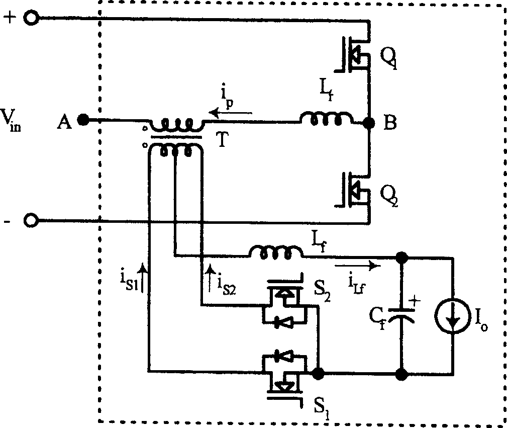
[0043] In order to clearly illustrate the detailed technical features of the prior art and the improved technology proposed by the present invention, the current and voltage changes after the primary-side synchronous rectifier is turned off are firstly analyzed here. Figure 10 is the detailed main waveform timing diagram, figure 2 is the main power asymmetrical half-bridge circuit topology corresponding to the waveform timing diagram.

[0044] see figure 2 , which is a topological structure diagram of an asymmetric control half-bridge circuit. Among them, the switching power converter has an input voltage source V in , a first switching device Q 1 and a second switching device Q 2 , a transformer T, and a first synchronous rectifier S 2 and a second synchronous rectifier S 1 A rectifier circuit. The first switching device Q 1 connected to the input voltage source V in the high voltage side, the second switching device Q 2 connected to the input voltage source V i...


PUM


Abstract

This invention relates to a switching power converter, and an controlling method used for a first synchronous rectifier and a second synchronous rectifier, the switching power converter comprises a transformer, a first on-off device and a second on-off device, the first one is serially connected with the second one and both are connected in parallel to a input voltage source, the first synchronous rectifier is linked to a low-pressure of a secondary side winding of the transformer, the second synchronous rectifier is linked to a high-pressure of the secondary side winding, the first on-off device is linked to a high-pressure of input voltage source, and the second on-off device is linked to a low-pressure. The controlling method comprises the following steps: driving the first on-off device to be on state and the second device to be off state; when the second on-off device is driven to be in on state, driving the second synchronous rectifier to be off state, making the power source convey from primary side winding to the secondary side winding.

Description

technical field [0001] The invention relates to a switching power converter and a control method for a synchronous rectifier thereof, in particular to a method and circuit for synchronous control of a zero-voltage switching DC / DC converter. Background technique [0002] The development trend of DC / DC converters, like most power products, is towards high efficiency, high power density, high reliability and low cost. cost) direction. In the traditional zero-voltage switching (ZVS) DC / DC converter rectified by diodes, the conduction loss of the rectifier diode usually accounts for 30-40% of the total loss. If you want to further improve the traditional ZVS DC / DC conversion To improve the efficiency of the rectifier, synchronous rectification technology must be applied to reduce the conduction loss of the rectifier. The application of synchronous rectification technology can greatly reduce the conduction loss of output rectification, but it also brings problems in the drive co...

Claims


Application Information

Patent Timeline
Patent Type & Authority Applications(China)
IPC IPC(8): H02J3/00H02J3/38
Inventor 言超叶浩屹吴洪洋曾剑鸿应建平
Owner DELTA ELECTRONICS INC
Why Eureka
Try Eureka