Lighting device and method thereof

A technology of lighting device and lighting method, applied in lighting device, electric lamp circuit arrangement, light source and other directions, can solve problems such as excessively low conduction time, and achieve the effect of prolonging conduction time and reducing stroboscopic flicker

Inactive Publication Date: 2012-12-12
DONGGUAN BOZE PHOTOELECTRIC TECH
View PDF4 Cites 6 Cited by
  • Summary
  • Abstract
  • Description
  • Claims
  • Application Information

AI Technical Summary

Problems solved by technology

More specifically, the too low conduction time of the light-emitting group 92 will make the stroboscopic phenomenon of the lighting device more obvious.

Method used


Image

  • Lighting device and method thereof
  • Lighting device and method thereof
  • Lighting device and method thereof

Examples


Embodiment 1

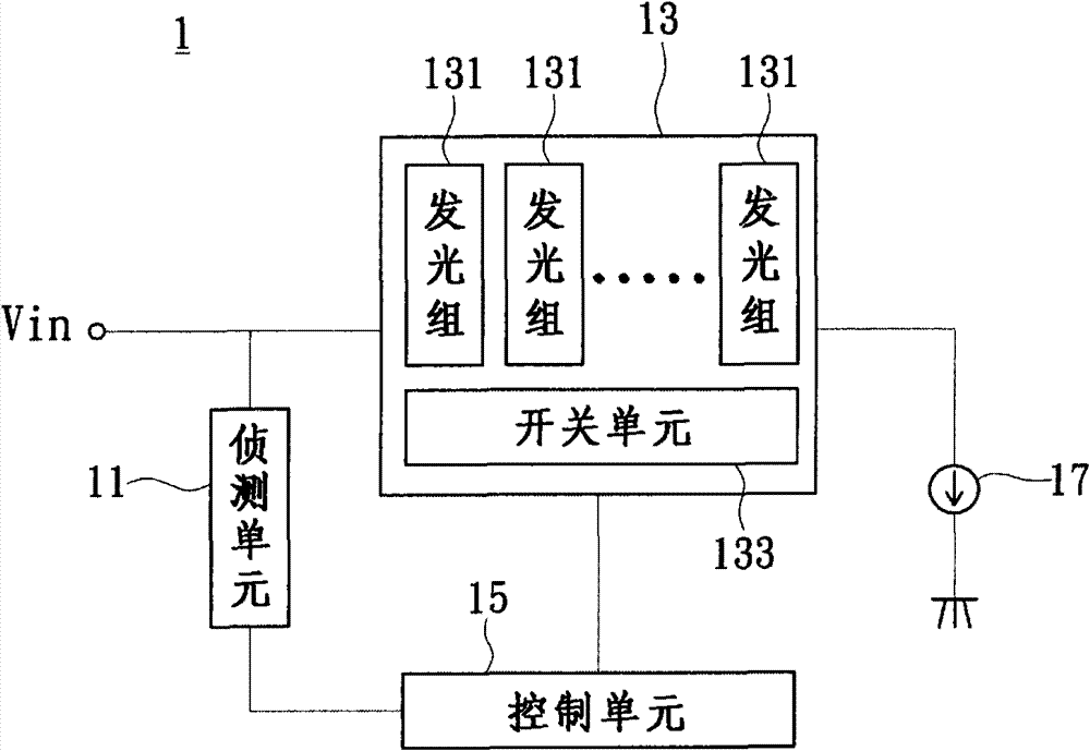
[0038] see figure 2 , which is a schematic block diagram of the lighting device according to Embodiment 1 of the present invention. The lighting device 1 may include a detection unit 11 , a light emitting unit 13 and a control unit 15 . The control unit 15 is coupled between the detection unit 11 and the light emitting unit 13 .

[0039] The detection unit 11 is used to detect the state of the input power Vin used by the light emitting unit 13 , for example, the detection unit 11 can know the phase change or the voltage change of the input power Vin. More specifically, the detection unit 11 may be a phase detection circuit or a voltage detection circuit, but the present invention is not limited thereto. The input power can be a pulsating direct current, for example, the pulsating direct current can be obtained after the AC power is rectified. Furthermore, the pulsating direct current terminal can be full-wave or half-wave pulsating direct current. The following descriptio...

Embodiment 2

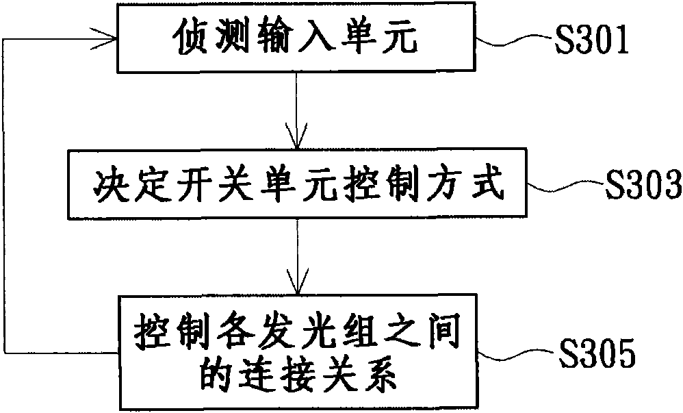
[0045] see image 3 , which is a flow chart of the lighting method according to Embodiment 2 of the present invention. in the description image 3 Please also refer to the process figure 2 The lighting fixture shown, image 3 The process includes the following steps:

[0046]The control unit 15 detects the input power through the detection unit 11 (eg, step S301 ) to know the state of the input power, such as the voltage state of the input power or the current phase position of the input power. According to the detection result of the detection unit 11, the control unit 15 judges whether there is a setting condition that meets the preset value, so as to determine the control mode of the switch unit 133 (eg step S303). When the preset value condition is met, the control unit 15 further controls the switch unit 133 to control the connection relationship between the light-emitting groups 131 according to the conduction voltage drop of the corresponding light-emitting unit 13...

Embodiment 3

[0048] see Figure 4 , which is a schematic block diagram of a lighting device combined with a power supply according to Embodiment 3 of the present invention. The lighting device 2 may include a rectifying unit 10 , a detecting unit 11 , a voltage stabilizing unit 12 , a light emitting unit 14 , a control unit 15 and a current source 17 . The rectification unit 10 is coupled to the detection unit 11 , the voltage stabilization unit 12 and the light emitting unit 14 respectively. The control unit 15 is coupled to the detection unit 11 , the voltage stabilizing unit 12 and the light emitting unit 14 respectively.

[0049] In the third embodiment, the rectifying unit 10 can be a full-wave rectifying circuit to rectify the waveform of the AC power to the input power available for the light-emitting unit 14, and the input power is a full-wave pulsating DC. It should be noted that the rectification unit 10 is not limited here, and may also be a half-wave rectification circuit.

...


PUM


Abstract

Disclosed are a lighting device and a method thereof. The lighting device is provided with an input power source which is a pulsation direct-current power source, and comprises a lighting unit, a detecting unit and a control unit. The lighting unit is provided with a plurality of lighting sets and switch units, wherein the switch units are used for connecting the lighting sets in series and/or parallel. The detecting unit is used for detecting states of the input power source input into the lighting unit. The control unit is coupled to the detecting unit and the switch units and controls the switch units according to detecting results of the detecting unit so as to enable conduction voltage of the lighting unit to vary along with the input power source. Accordingly, the conduction voltage of the lighting unit can be adjusted, and conduction time of the lighting unit within a period of the input power source is prolonged.

Description

technical field [0001] The present invention relates to an illuminating device and a method, in particular to an illuminating device and a method of a light emitting diode. Background technique [0002] Due to the characteristics of low power consumption, high brightness and long life, light emitting diodes have been gradually and widely used in various lighting devices. see figure 1 , which is a schematic diagram of the lighting device. The lighting device includes a rectifier circuit 90, a light-emitting group 92 and a current source 94. The light-emitting group 92 is composed of a plurality of light-emitting diodes connected in series. The rectification circuit 90 is described here as a full-wave rectification circuit, so the AC power supply can obtain pulsating direct current through the rectification circuit 90, and the pulsating direct current is used as the input power for supplying the light-emitting diodes. When a plurality of LEDs connected in series are turned ...

Claims


Application Information

Patent Timeline
Patent Type & Authority Applications(China)
IPC IPC(8): H05B37/02
CPCY02B20/42H05B45/44
Inventor 戴世能钟嘉珽
Owner DONGGUAN BOZE PHOTOELECTRIC TECH
Why Eureka
Try Eureka