Multi-processor power management system and method as well as intelligent terminal

A power management system, multi-processor technology, applied in the direction of data processing power supply, electrical digital data processing, digital data processing components, etc. The effect of reducing processor damage

Active Publication Date: 2016-07-20
ZHONGTIAN BROADBAND TECH
View PDF4 Cites 6 Cited by
  • Summary
  • Abstract
  • Description
  • Claims
  • Application Information

AI Technical Summary

Problems solved by technology

[0004] The purpose of the present invention is to provide a multiprocessor power management system and method to solve the technical problem of performance degradation caused by excessive temperature when using multiprocessors

Method used


Image

  • Multi-processor power management system and method as well as intelligent terminal
  • Multi-processor power management system and method as well as intelligent terminal
  • Multi-processor power management system and method as well as intelligent terminal

Examples


Embodiment 1

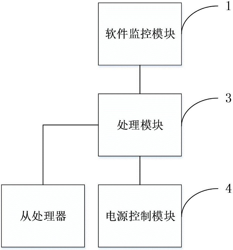
[0078] Such as figure 1 As shown, in the multiprocessor power management system of the present invention, the multiprocessor includes a master processor and a slave processor, and the multiprocessor power management system includes a software monitoring module 1, a processing module 3 and a power control module 4;

[0079] Wherein, the software monitoring module 1 is connected with the processing module 3, and the processing module 3 is respectively connected with the power control module 4 and each slave processor;

[0080] Software monitoring module 1, used for real-time monitoring of the usage status of each slave processor;

[0081] The processing module 3 is used to judge whether each slave processor is in an idle or overloaded state;

[0082] The power control module 4 is used to control the power on and off of each slave processor;

[0083] Processing module 3 judges whether each slave processor is in idle or overload state according to each slave processor usage stat...

Embodiment 2

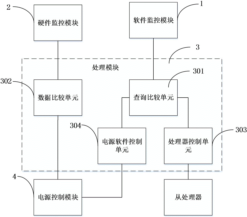
[0086] Such as figure 2 As shown, the multiprocessor power management system of the present invention includes a software monitoring module 1, a hardware monitoring module 2, a processing module 3 and a power control module 4;

[0087] Wherein, the processing module 3 includes a query comparison unit 301, a data comparison unit 302, a processor control unit 303 and a power supply software control unit 304;

[0088] The software monitoring module 1 is connected with the query comparison unit 301, and the hardware monitoring module 2 is connected with the data comparison unit 302; the query comparison unit 301 is connected with the processor control unit 303 and the power supply software control unit 304 respectively; the processor control unit 303 is connected with each slave processing The device is connected; the power software control unit 304 is connected with the power control module 4; the data comparison unit 302 is connected with the power control module 4;

[0089] S...

Embodiment 3

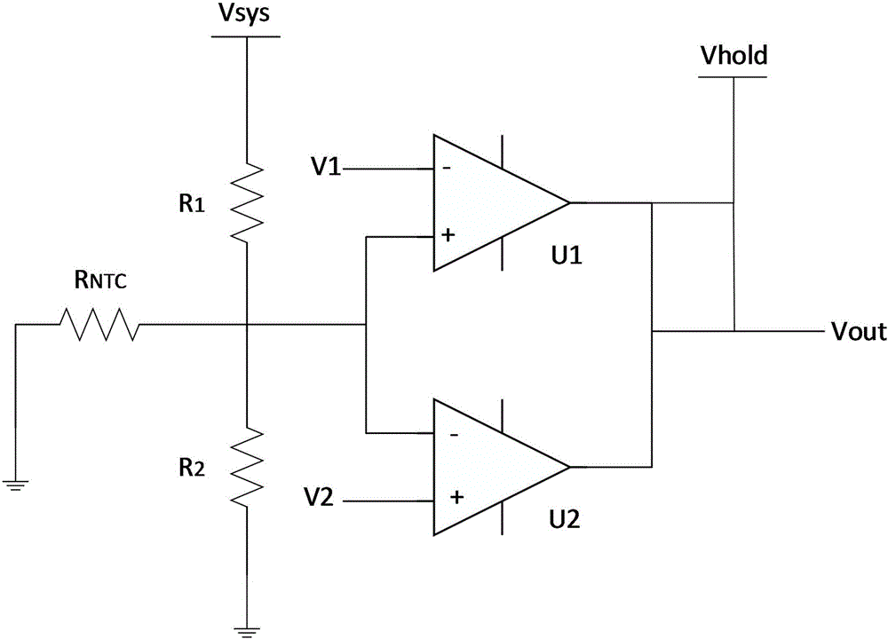
[0101] Such as image 3 As shown, the data comparison unit 302 in the processor power management circuit of the present invention includes a resistor R1, a resistor R2, a comparator U1, and a comparator U2; the negative temperature coefficient resistor R NTC One end is connected to the analog ground, the negative temperature coefficient resistor R NTC The other end of the resistor R1 is connected to one end of the resistor R1, one end of the resistor R2, the positive input end of the comparator U1 and the negative input end of the comparator U2, the other end of the resistor R1 is connected to the system power supply Vsys, and the other end of the resistor R2 is connected to the analog Connect to ground, the negative input terminal of comparator U1 is connected to the lower limit voltage V1 of the system, the positive input terminal of comparator U2 is connected to the upper limit voltage V2 of the system, and the output terminal of comparator U1 is respectively connected to t...


PUM


Abstract

The invention discloses a multi-processor power management system. Multiple processors include a main processor and auxiliary processors; the multi-processor power management system comprises software monitoring modules, processing modules and power control modules; the software monitoring modules are used for monitoring the service condition of each auxiliary processor in real time; the processing modules are used for judging whether each auxiliary processor is in an idle or overload state; the power control modules are used for controlling on-off of a power supply of each auxiliary processor; according to the auxiliary processor service conditions acquired by the software monitoring modules in real time, when the auxiliary processors are in the idle state, the processing modules perform system restart on the auxiliary processors, and when the auxiliary processors are in the overload state, the processing modules shut off the power supplies of the auxiliary processors through the power control modules. The service conditions of the auxiliary processors are monitored by software, and the power states of the auxiliary processors are controlled according to the service conditions, so that the technical effects of actual shut off of the power supplies of the auxiliary processors and reduction of emitted heat are realized.

Description

technical field [0001] The invention relates to a multiprocessor power management system, method and intelligent terminal. Background technique [0002] Now more and more handheld terminal products, including MIFI, smartphones, smart routers, smart charging treasures, etc., have begun to use dual processors (hereinafter referred to as "CPU") in order to ensure higher performance and computing speed. Even three CPUs. [0003] However, the following problems are also more obvious. The number of CPUs increases, the power consumption of the motherboard increases, the corresponding power consumption increases, and the heat generation increases. For terminal products with independent shell designs, heat dissipation has become an urgent problem to be solved. . The way to solve this problem in the prior art is to strive for heat dissipation space as much as possible in the structure. Since the current circuit design is more and more inclined to integration and high-quality product...

Claims


Application Information

Patent Timeline
Patent Type & Authority Applications(China)
IPC IPC(8): G06F1/32G06F21/81H02H5/04
CPCG06F1/28G06F1/3287G06F21/81H02H5/04
Inventor 许梦
Owner ZHONGTIAN BROADBAND TECH
Why Eureka
Try Eureka