BUCK converter bootstrap drive circuit based on narrow pulse control

A bootstrap drive circuit and drive circuit technology, which are used in control/regulation systems, output power conversion devices, conversion of DC power input to DC power output, etc.

Active Publication Date: 2021-01-01
河南嘉晨智能控制股份有限公司
View PDF4 Cites 5 Cited by
  • Summary
  • Abstract
  • Description
  • Claims
  • Application Information

AI Technical Summary

Problems solved by technology

When the load is heavy or the inductor current is continuous, the bootstra...

Method used


Image

  • BUCK converter bootstrap drive circuit based on narrow pulse control
  • BUCK converter bootstrap drive circuit based on narrow pulse control
  • BUCK converter bootstrap drive circuit based on narrow pulse control

Examples


Embodiment Construction

[0030] A detailed description will be given below in conjunction with the accompanying drawings.

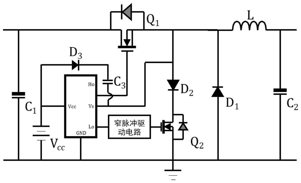
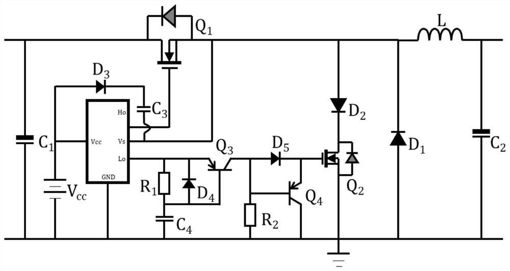
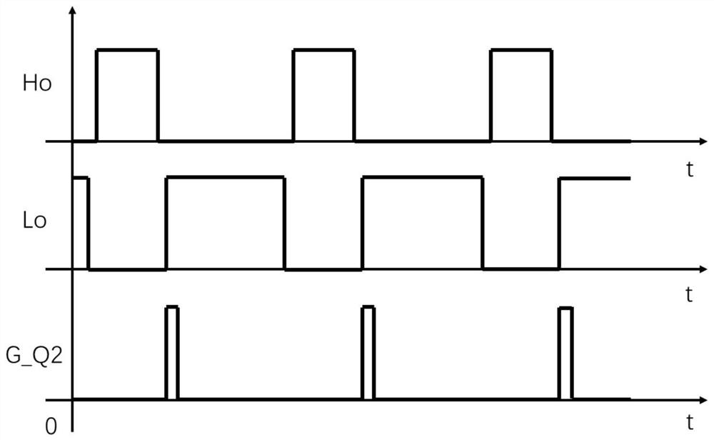
[0031] Preferably, the technical problems of the present invention are described in detail. For the synchronous rectification type BUCK converter bootstrap drive circuit, when the BUCK circuit is in a light-load / no-load state, the energy storage inductor L will enter the current discontinuous working mode. At this time the output filter capacitor C 2 Discharging through the energy storage inductor L and the added bootstrap charging circuit will generate a large negative current, which will cause additional loss. At the same time, if the negative current is overloaded, the added MOS tube (such as the secondary switch tube Q 2 ) and diodes need to use high-current MOS tubes and diodes, which increases the cost of the device. Specifically, as figure 1 , Figure 4 and Figure 5 As shown, when the BUCK circuit is in the light-load / no-load state, the current may cross zero. In s...


PUM


Abstract

The invention relates to a BUCK converter bootstrap driving circuit based on narrow pulse control, which at least comprises a BUCK circuit, a bootstrap charging branch and a driving chip for driving the bootstrap charging branch are connected in the BUCK circuit, and when the BUCK circuit is in a light-load/no-load state and the duty ratio of a main switching tube of the BUCK circuit is less thana first threshold, the driving chip reduces the conduction time of an auxiliary switch tube in the bootstrap charging branch circuit based on a narrow pulse driving mode so as to prevent the BUCK circuit and the bootstrap charging branch circuit from generating negative current or reduce the negative current in the BUCK circuit and the bootstrap charging branch circuit.

Description

technical field [0001] The invention relates to the technical field of switching power supplies, in particular to a bootstrap drive circuit for a BUCK converter based on narrow pulse control. Background technique [0002] The BUCK circuit is widely used in various step-down application scenarios due to its simple topology. BUCK circuit is also called step-down circuit BUCK converter, its basic feature is a DC-DC conversion circuit, the output voltage is lower than the input voltage. BUCK converter is a non-isolated DC converter. The input current of the BUCK converter is pulsating, and the output current is continuous. Figure 4 The circuit shown as the most basic BUCK converter can also be called the basic topology of the BUCK converter. BUCK converter generally includes the main switching tube Q 1 , Freewheeling diode D 1 , energy storage inductor L, output filter capacitor C 2 and the input filter capacitor C 1 . Input filter capacitor C 1 One side is connected to...

Claims


Application Information

Patent Timeline
IPC IPC(8): H02M3/155H02M1/08H02M1/36
CPCH02M1/08H02M1/36H02M3/155H02M1/0032H02M1/0054Y02B70/10
Inventor 江小龙李飞姚欣
Owner 河南嘉晨智能控制股份有限公司
Why Eureka
Try Eureka