A method and circuit for adaptive control of active clamp flyback converter

A flyback converter, self-adaptive control technology, applied in control/regulation systems, conversion of DC power input to DC power output, instruments, etc., can solve the deviation of integrated capacitor capacitance value, not to mention self-adaptive, and consistent circuit Sexual issues, etc.

CN108809107BActive Publication Date: 2019-08-23SHENZHEN NANYUN MICROELECTRONICS CO LTD +1
6 Cites 0 Cited by

Patent Information

Authority / Receiving Office
CN · China
Patent Type
Patents(China)
Current Assignee / Owner
Publication Date
2019-08-23

Smart Images

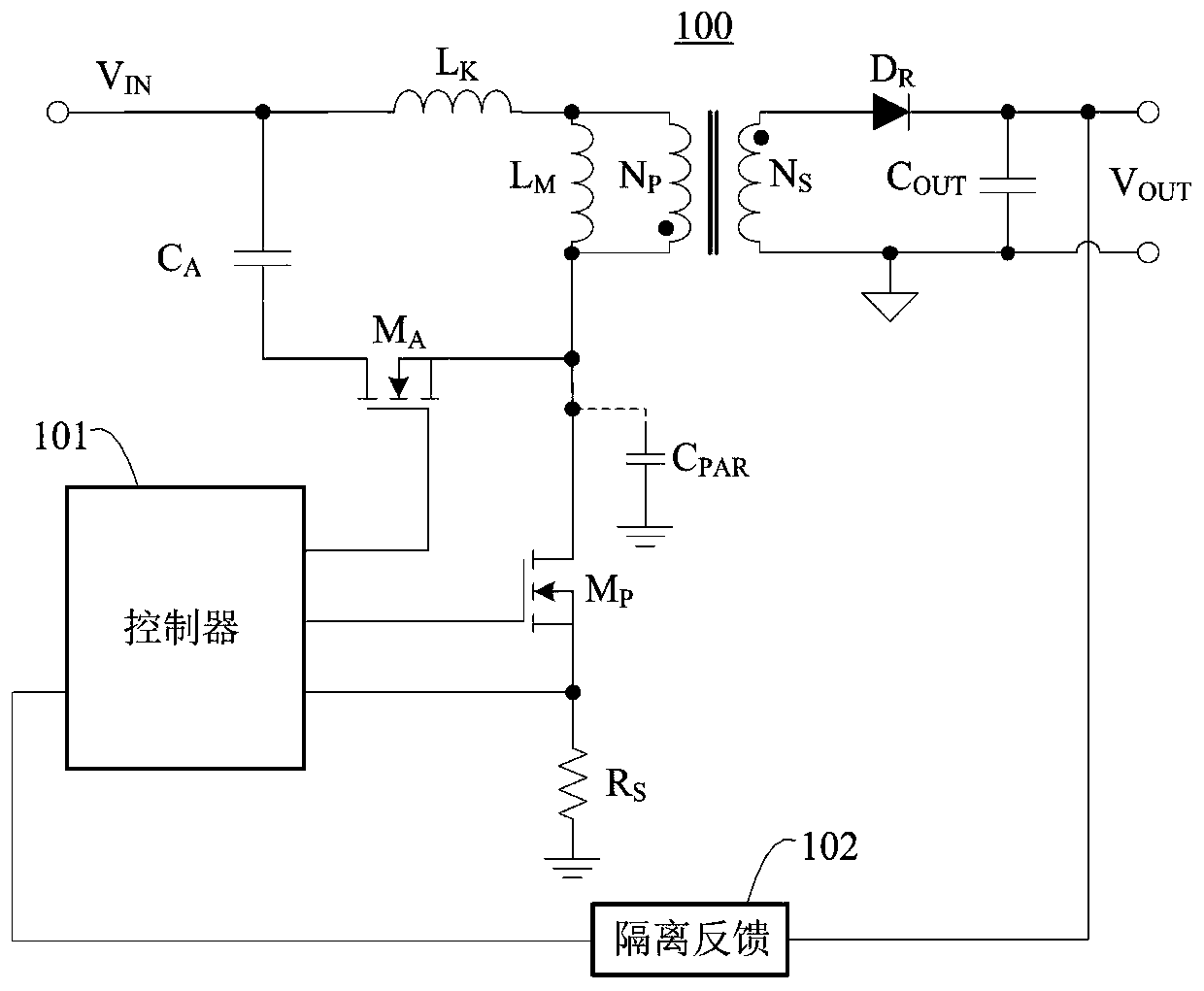
  • Figure 1
    Figure 1
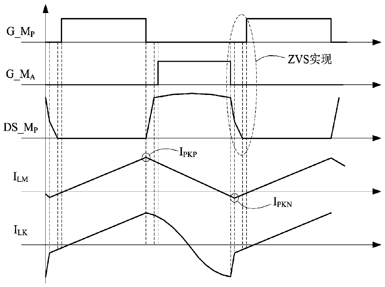
  • Figure 2
    Figure 2
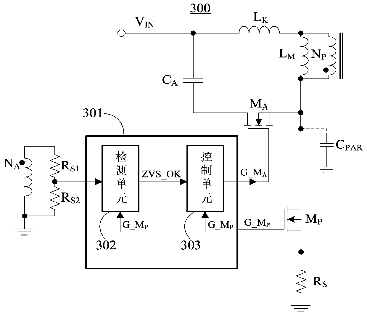
  • Figure 3
    Figure 3
Patent Text Reader

Abstract

The invention provides an active clamp flyback converter self-adaptive control method and circuit, which are used for controlling a conduction time of a clamper tube. The active clamp flyback converter self-adaptive control method and circuit have the following characteristics and effects: a multiplexing auxiliary winding voltage sampling pin determines whether a main switch pipe ZVS is switched on or not, and no additional pin is needed, so that the encapsulation size is reduced; a switch node voltage proportional value in the conduction period of the main switch pipe is saved, and the conduction realization situation of ZVS is determined cycle by cycle on a rising edge of a main switch pipe driving signal, so that the self adaption can be actually realized; since the saved switch node voltage proportional value is gradually updated cycle by cycle, the determination result of the conduction realization situation of the main switch pipe ZVS is not influenced by the device precision, and the determination result is more accurate; and by virtue of the bidirectional control for the width of the clamper pipe driving signal, on the premise of realizing the conduction of the main switchpipe ZVS, the negative current flowing by a diode of the main switch pipe body can be reduced as far as possible, and the loss can be reduced.
Need to check novelty before this filing date? Find Prior Art

Description

technical field

[0001] The invention relates to a method and a circuit for adaptive control of a clamp tube, in particular to a method and a circuit for adaptive control of a clamp tube in an active clamp flyback converter. Background technique

[0002] Flyback converters are widely used in small and medium power off-line switching power supplies due to their low cost and simple topology. In the actual working process, the energy of the primary side of the flyback converter cannot be completely transferred to the secondary side, and the energy left on the primary side is resonated at the switching node, that is, the drain end of the main switching tube, through the leakage inductance and the parasitic capacitance of the switching node. Very high voltage spikes. In order to reduce the voltage stress of the switch tube, a snubber circuit is needed. Conventional snubber circuits include RCD clamping circuits, LCD clamping circuits and active clamping circuits. Among them, the...

Examples

Embodiment 1

[0033] Such as image 3 As shown, an adaptive control circuit of an active clamp flyback converter includes a detection unit circuit 302 and a control unit circuit 303. 302 passes through the auxiliary winding N A and voltage divider resistor R S1 / R S2 Indirectly sample the switch node voltage, and output a ZVS judgment signal ZVS_OK to 303 . Assuming the switch node voltage is V DS_MP , the voltage difference across the magnetizing inductance is V IN -V DS_MP , auxiliary winding N A The terminal voltage is The current drawn from the detection unit 302 is When the main switch realizes ZVS turn-on, that is, the drain voltage of the main switch has been pulled to the ground potential before it is turned on, V DS_MP Approximately 0V. In the main switch tube M P During the conduction period, the drain terminal voltage is also approximately at the ground potential. In this way, the M P During the conduction period, the current flowing from the detection unit is sampl...