Magneto-resistive sensor

Inactive Publication Date: 2010-02-11
NXP BV
View PDF9 Cites 43 Cited by
  • Summary
  • Abstract
  • Description
  • Claims
  • Application Information

AI Technical Summary

Benefits of technology

[0014]An advantage of integrating the element in the second substrate, e.g., the laminate, is that the element, e.g., the compensation coil and/or flip coil, does not need to affect the effective size of the first substrate, e.g., the die size of the sensor. One of the known implementations of an MR sensor in EP 0 544 479 has the auxiliary coils implemented in the die itself, thus requiring the size of the sensor die to be large enough that the coils can be accommodated, which leads to extra costs. Another one of the known implementations in EP 0 544 479 uses a current strap. The geometric configurations with straps may not be

Problems solved by technology

In addition, the simple sensor cannot discriminate between external

Method used


Image

  • Magneto-resistive sensor
  • Magneto-resistive sensor
  • Magneto-resistive sensor

Examples


Embodiment Construction

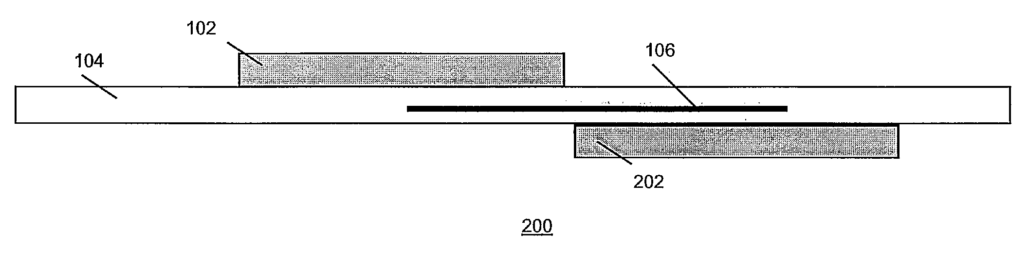
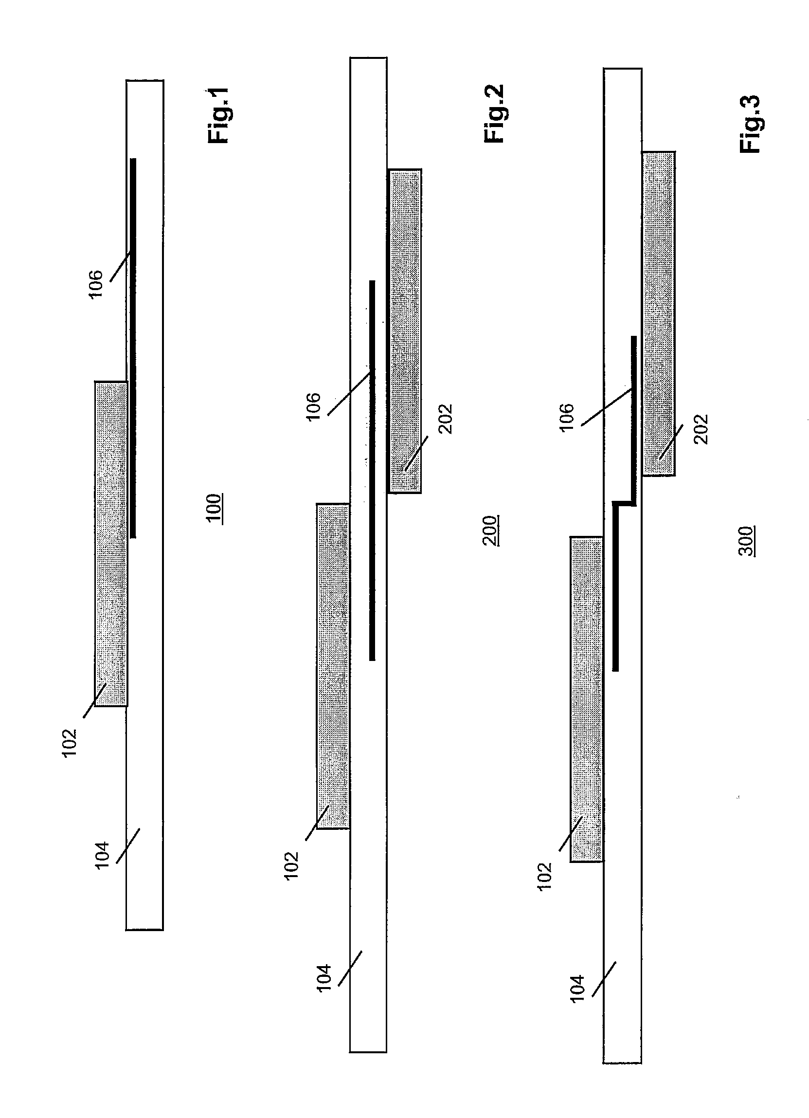
[0022]The invention relates to a high-performance, integrated MR sensor that is realized by adding compensation and / or flipping coils that enable signal conditioning of the sensor output. Compensation and flipping coils are usually added in metal layers on top of the sensitive layers that form the MR sensor in an integrated circuit technology. In the invention, however, at least one of the coils is positioned in the laminate that connects the MR sensor, with its IC, within a single package. Accordingly, the die area of the MR sensor, and hence the package size, can be kept at minimum dimensions, resulting in low-cost and a competitive advantage.

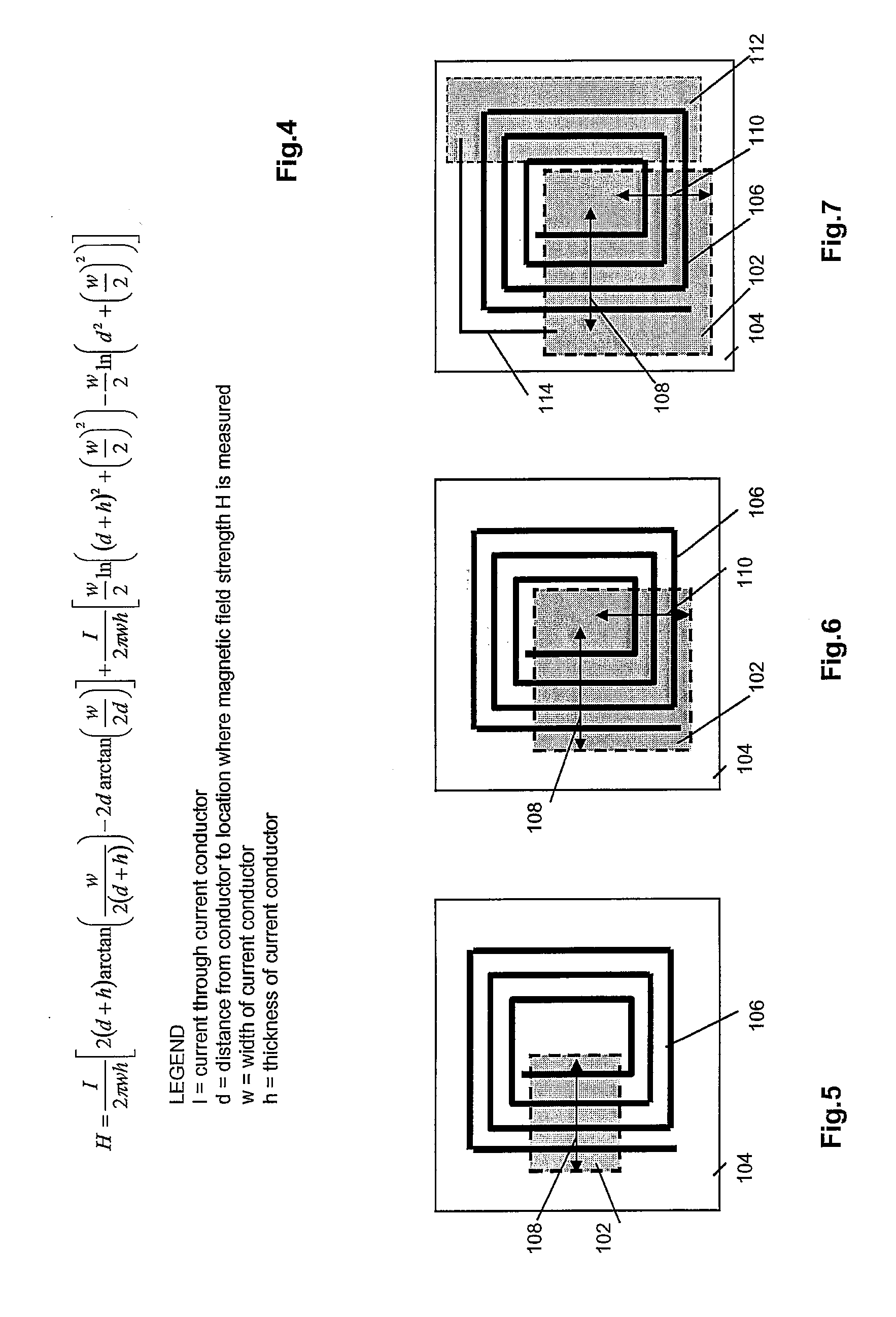
[0023]A compensation coil enables to set a magnetometer in a nulling mode, wherein the external magnetic field is compensated internally by a current flowing through the compensation coil. In essence, the compensation coil is able to generate magnetic fields in the sensitive direction of the sensor. As a result, the compensation coil allows f...


PUM


Abstract

A high-performance, integrated AMR sensor has compensation and flipping coils for signal conditioning of the sensor output. At least one of the coils is formed in the laminate that connects the AMR sensor with its IC within a single package. As a result, the dimensions of the die area of the AMR sensor and the package size can be kept small.

Description

FIELD OF THE INVENTION[0001]The invention relates to a circuit with a magneto-resistive sensor.BACKGROUND OF THE INVENTION[0002]Magneto-resistance (MR) is a material property of a whole family of ferromagnetic alloys that refers to a dependence of electrical resistance on the angle between the direction of the electrical current flowing through the material and the orientation of an external magnetic field relative to the direction of the current. The effect is attributed to a larger probability of s-d scattering of electrons in the direction of the magnetic field. The net effect is that the electrical resistance maximum value when the direction of current is parallel to the applied magnetic field. An example of such material is a ferromagnetic material called “permalloy” (19% Fe, 81% Ni).[0003]MR materials can be used to create magnetic field sensors, also referred to as magneto-meters. Operation and examples of such sensors are described in Application Note AN 00022 “Electronic Co...

Claims


Application Information

Patent Timeline
IPC IPC(8): G01R33/09
CPCB82Y25/00H01L43/08G01R33/096G01R33/093H10N50/10
Inventor BOEVE, HANSJANSEN, STEPHANIKKINK, TEUNIS JANDURIC, HARRIS
Owner NXP BV
Why Eureka
Try Eureka