Exhaust gas waste heat recovery

a waste heat recovery and exhaust gas technology, applied in the direction of combustion-air/fuel-air treatment, liquid displacement, separation process, etc., can solve the problems of unsatisfactory heat transfer, large waste of energy from combustion, and need for additional package space for bypass pipes and heat exchangers, so as to improve fuel economy and vehicle emissions, the effect of fast engine warm up and faster passenger cabin heating

Inactive Publication Date: 2011-04-12
GM GLOBAL TECH OPERATIONS LLC
View PDF8 Cites 44 Cited by
  • Summary
  • Abstract
  • Description
  • Claims
  • Application Information

AI Technical Summary

Benefits of technology

[0007]An advantage of an embodiment is that faster engine warm up is achieved, which may improve fuel economy and vehicle emissions.
[0008]An advantage of an embodiment is that faster warming of a passenger cabin is achieved.
[0009]An advantage of an embodiment is that thermal transfer from the exhaust gasses to the engine coolant can be prevented when thermal input to the coolant is not desired. This is also accomplished with a relatively small package size in order to avoid interference with other vehicle components. Moreover, no moving parts are required for switching between a mode for transferring heat from the exhaust gasses to the engine coolant and one where heat transfer is prevented. This may lead to improved quality.
[0010]An advantage of an embodiment is that there is no pressure drop variation or other backpressure variation in the exhaust system when switching between a heat transfer mode and a non-heat transfer mode.

Problems solved by technology

When operating an internal combustion engine, a significant portion of the energy from the combustion is wasted as heat in the exhaust gasses expelled to atmosphere.
However, there may be certain operating conditions where this is not desirable.
For example, heat transfer may be undesirable if additional heat transfer may cause the liquid to boil, in which case the powertrain cooling system would need to have a higher capacity (larger radiator and fan) to prevent this.
But such systems require additional package space for bypass pipes and heat exchangers as well as valves (and actuators for the valves) for redirecting the flow.
Moreover, by diverting the exhaust gasses, there may be undesirable pressure drop variations in the exhaust system or undesirable changes in exhaust back pressure when switching from one flow path to another.

Method used


Image

  • Exhaust gas waste heat recovery
  • Exhaust gas waste heat recovery
  • Exhaust gas waste heat recovery

Examples


second embodiment

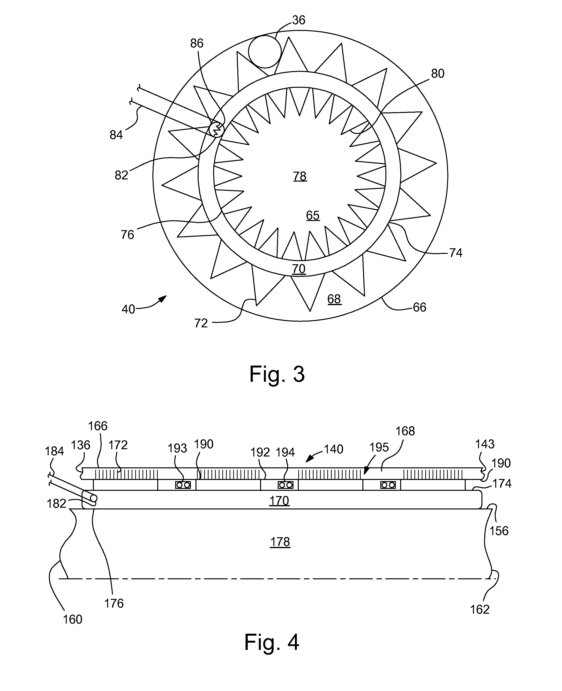
[0025]FIG. 4 illustrates a Since this embodiment is similar to the first, similar element numbers will be used for similar elements, but employing 100-series numbers.

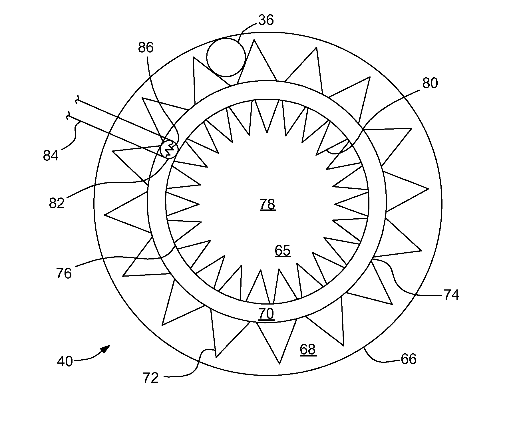
[0026]In this embodiment, the intermediate exhaust pipe 156 forms or connects to the inner wall 176 of the vacuum chamber 170 to define the exhaust chamber 178 between the exhaust inlet 160 and the exhaust outlet 162 of the exhaust heat recovery heat exchanger 140. The vacuum chamber 170 is formed between the inner wall 176 and outer wall 174, with the hydride pellet 182 mounted therein and connected to electrical leads 184. The housing 166 forms an outer wall of a coolant chamber 168, between the coolant inlet 136 and coolant outlet 143, with coolant heat transfer fins 172 for increasing the surface area for heat transfer.

first embodiment

[0027]Unlike the first embodiment, this embodiment includes components between the outer wall 174 of the vacuum chamber 170 and an inner wall 190 of the coolant chamber 168. Thermoelectric devices 191 alternate with pockets of insulating material 192 and high temperature electrical conductors 193 in potting material 194 to create an electrical power generating assembly 195. The potting material 194 helps protect the electrical conductors 193 from the heat, while the insulation may be employed to reduce the heat transfer directly to the coolant (rather than through the thermoelectric devices 191). The thermoelectric devices 191 are oriented to have their hot sides facing the exhaust chamber 178 and their cold sides facing the coolant chamber 168.

[0028]When no heat transfer from the exhaust gasses is desired, the operation is the same as with the first embodiment. No electric current is supplied to the electric leads 184, so the hydride pellet 182 retains the hydrogen, making the vacu...

third embodiment

[0029]FIG. 5 illustrates a Since this embodiment is similar to the first, similar element numbers will be used for similar elements, but employing 200-series numbers. The elements discussed in this embodiment may be used in a vehicle or in stationary equipment.

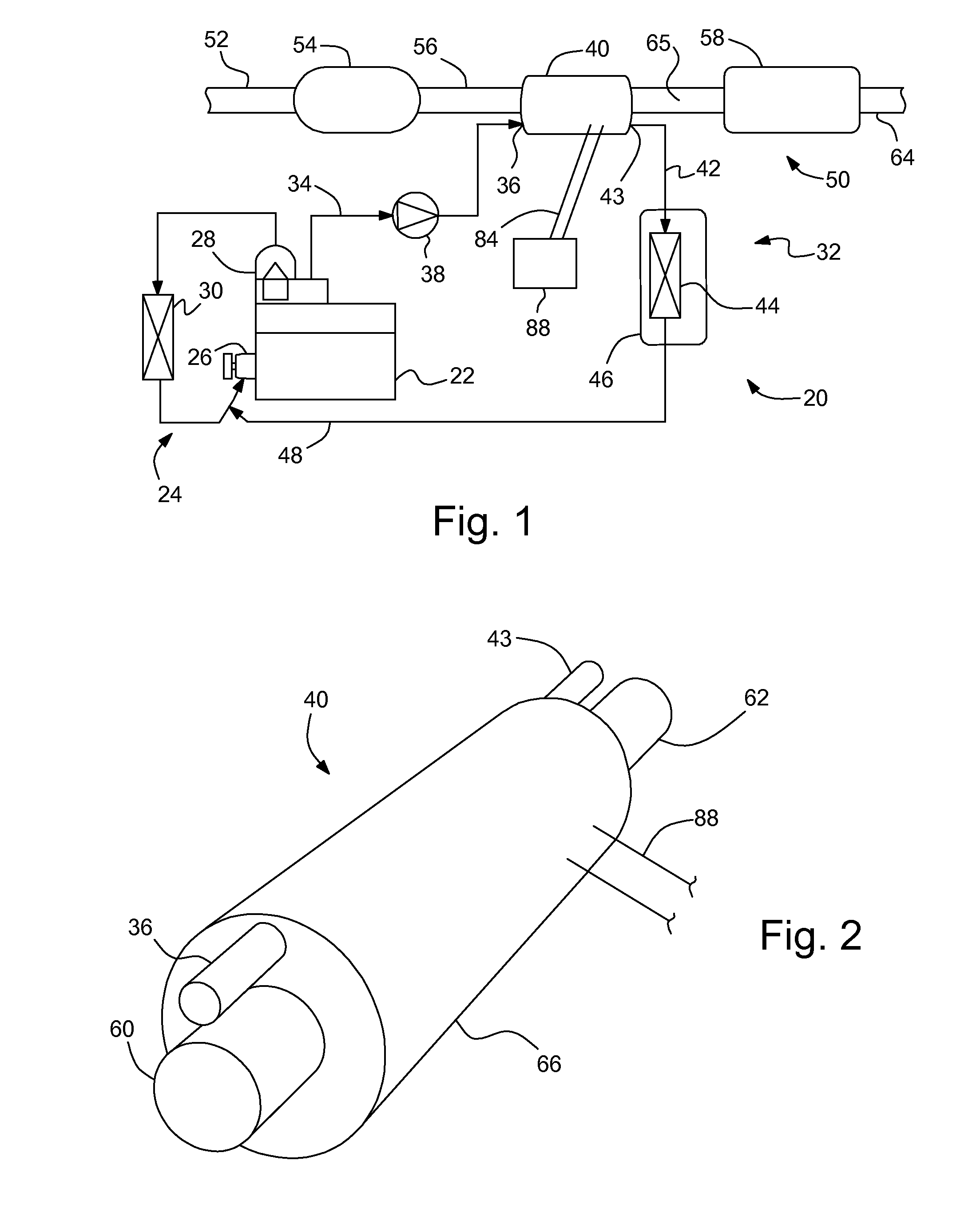
[0030]In this embodiment, an assembly 222 that produces hot waste fluids, such as, for example, an engine, produces the hot fluids, such as exhaust gasses, that are directed through the pipe 252, an optional exhaust (or other fluid) treatment assembly 254, intermediate pipe 256, exhaust heat recovery heat exchanger 240, and an optional muffler 258 and tailpipe 264 (if for an engine exhaust system). Alternatively, the assembly 222 may be, for example, fuel cells. In this embodiment, the conduit 234 leading into the heat exchanger 240 may carry water or refrigerant (or other heat absorbing fluid) that is then directed through the second conduit 242 to a machine 296 driven by the hot fluid, such as, for example, a turbine. The t...


PUM

PropertyMeasurementUnit
electrical currentaaaaaaaaaa
electric currentaaaaaaaaaa
heataaaaaaaaaa

Abstract

An exhaust heat recovery heat exchanger assembly for use along a main exhaust flow path of an exhaust system for an engine, and a method of operation, is disclosed. The exhaust heat recovery heat exchanger includes a sealed vacuum chamber, including a hydride pellet mounted in the chamber, and electrical leads extending from the hydride pellet. An exhaust chamber along the main exhaust flow path is located along an inner wall of the vacuum chamber. A housing surrounds the vacuum chamber and defines a heat receiving medium chamber. A heat receiving medium flows through the heat receiving medium chamber and absorbs heat from the exhaust flowing through the exhaust chamber when an electric current is applied to the hydride pellet.

Description

BACKGROUND OF INVENTION[0001]The present invention relates generally to waste heat recovery and use of recovered waste heat from a fluid such as the exhaust of a vehicle engine.[0002]When operating an internal combustion engine, a significant portion of the energy from the combustion is wasted as heat in the exhaust gasses expelled to atmosphere. Some have proposed systems for recovering exhaust gas waste heat in vehicles, such as transferring exhaust gas heat to engine coolant. However, there may be certain operating conditions where this is not desirable. For example, heat transfer may be undesirable if additional heat transfer may cause the liquid to boil, in which case the powertrain cooling system would need to have a higher capacity (larger radiator and fan) to prevent this.[0003]Accordingly, some have suggested vehicle systems to allow for selectively transferring heat from the exhaust gasses to the engine coolant. For example, some vehicle exhaust systems include bypass pipe...

Claims


Application Information

Patent Timeline
Patent Type & Authority Patents(United States)
IPC IPC(8): F01N3/02
CPCF01N5/025F01N13/146F02G5/02F01N2240/02F01P2060/08F01P2060/16F01P2060/18Y02T10/16Y02T10/166Y02T10/12
Inventor MAJOR, GREGORY A.
Owner GM GLOBAL TECH OPERATIONS LLC
Why Eureka
Try Eureka