Engine coolant pump drive system and apparatus for a vehicle

a technology of engine cooling and drive system, which is applied in the direction of engine cooling apparatus, control devices for cooling apparatus, machines/engines, etc., can solve the problems of increasing the loss of coolant system, increasing fuel consumption, and continuous losses

Active Publication Date: 2007-10-11
GM GLOBAL TECH OPERATIONS LLC
View PDF6 Cites 20 Cited by
  • Summary
  • Abstract
  • Description
  • Claims
  • Application Information

AI Technical Summary

Problems solved by technology

Since the pump is driven directly by the engine using a belt, its speed is determined by that of the engine, and it operates continuously as long as the engine is running, resulting in continuous losses due to constant operation and constant circulation of the coolant fluid through the cooling loop, whether the cooling action is needed or not.
This results in much higher pump flow at higher engine speeds than is necessary, further increasing the losses in the coolant system, w...

Method used


Image

  • Engine coolant pump drive system and apparatus for a vehicle
  • Engine coolant pump drive system and apparatus for a vehicle
  • Engine coolant pump drive system and apparatus for a vehicle

Examples


Embodiment Construction

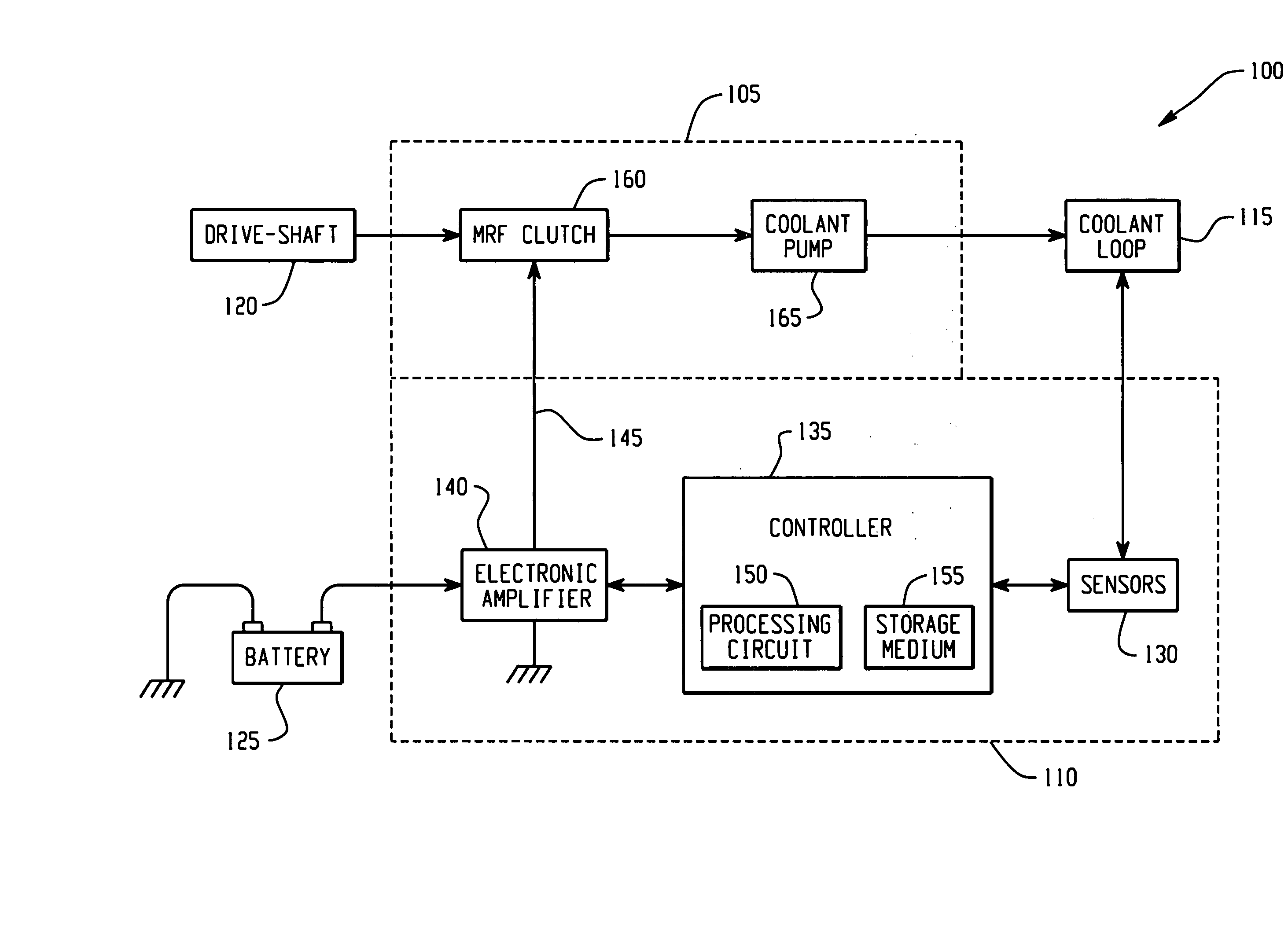
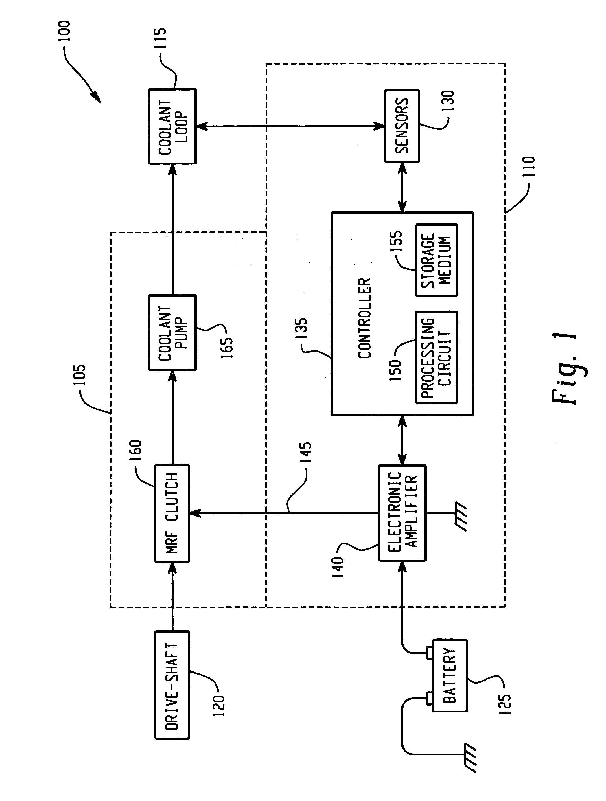
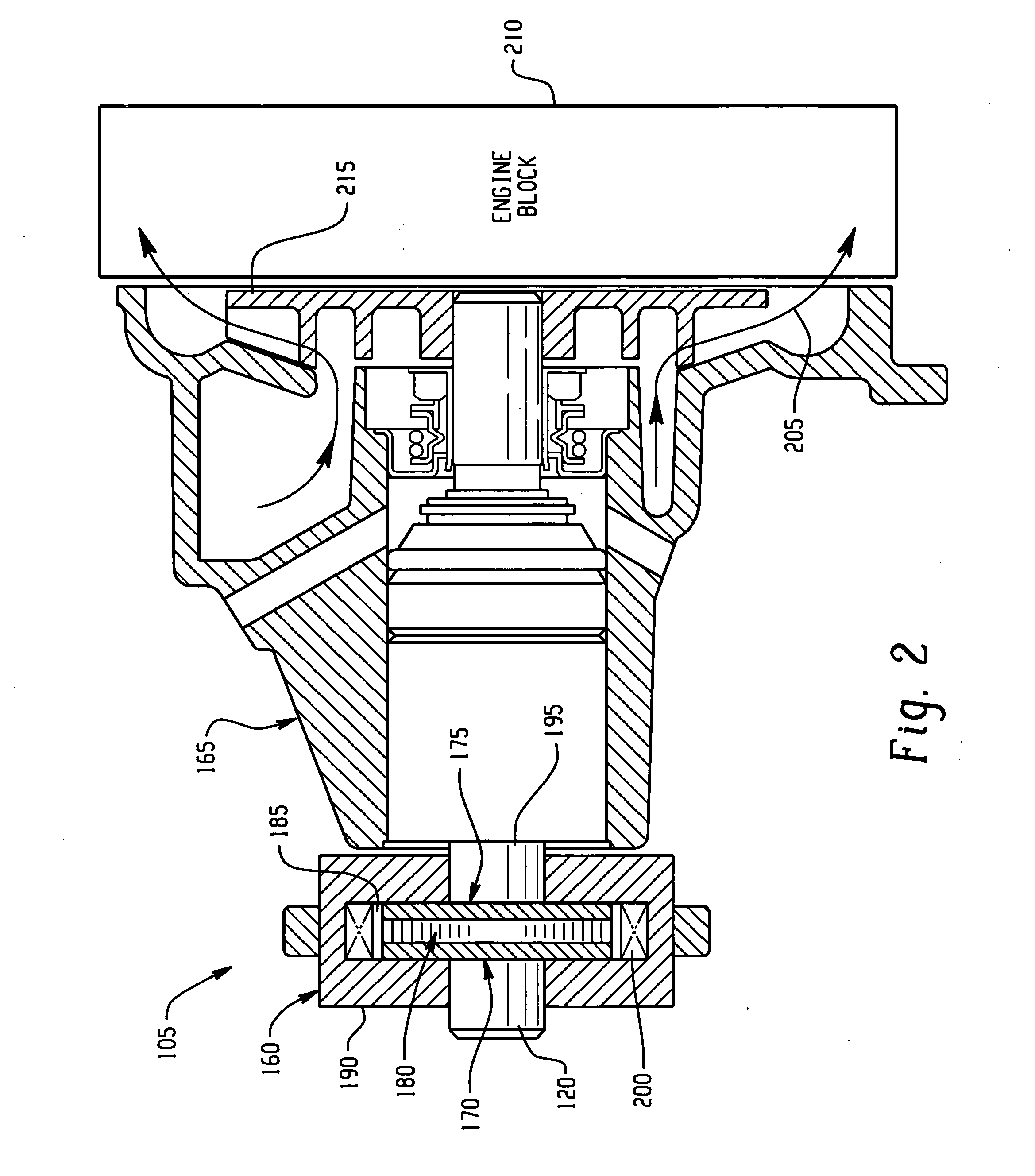
[0011] An embodiment of the invention provides a means to directly control the speed of an engine driven coolant pump by using a magnetorheological fluid (MRF) coupling (clutch) integrated between an accessory drive of the engine and the engine coolant pump. The MRF clutch provides for a continuously adjustable pump speed by controlling the torque transmitted from the engine drive shaft to that of the engine coolant pump. The MRF clutch may be part of the pump assembly or part of a pulley assembly.

[0012] An electronic controller is used to interface engine sensors (engine rpm, throttle angle, manifold absolute pressure, coolant temperature, engine cylinder head temperature, for example) and vehicle sensors (speed, accelerator pedal position, brake pedal position, for example) with an electronic amplifier to generate a current signal to an excitation coil embedded in the MRF clutch, thereby enabling the speed of the pump to vary in a continuous manner. It is also envisioned that an ...


PUM


Abstract

An engine coolant pump drive system for a vehicle having an engine, an engine coolant system, and at least one sensor for sensing at least one operational condition of the vehicle is disclosed. The pump drive system includes a magnetorheological fluid (MRF) clutch, and a coolant pump. The MRF clutch includes a torque input section coupled to a torque output section via a MRF, the torque input section being configured to receive a torque input from the engine. The coolant pump is configured for operable communication with the torque output section of the MRF clutch. In response to a signal from the at least one sensor, the MRF clutch is configured to provide a continuously variable torque transfer from the torque input section to the torque output section, thereby providing for variable coolant flow in the engine coolant system via the coolant pump capable of a continuously variable speed.

Description

BACKGROUND OF THE INVENTION [0001] The present disclosure relates generally to an engine coolant pump drive system and apparatus, and particularly to a variable speed engine coolant pump drive system and apparatus. [0002] A typical engine cooling system employs an engine driven water pump, driven by a belt for example, for circulating coolant fluid, such as a water-glycol mixture for example, that is circulated through the engine block and the radiator. Since the pump is driven directly by the engine using a belt, its speed is determined by that of the engine, and it operates continuously as long as the engine is running, resulting in continuous losses due to constant operation and constant circulation of the coolant fluid through the cooling loop, whether the cooling action is needed or not. Also, the pump has to be designed to provide the required flow and pressure for the worst-case engine speed, which could be near idle or during high grade towing. This results in much higher pu...

Claims


Application Information

Patent Timeline
IPC IPC(8): F01P5/10
CPCF01P5/12F01P2037/02F01P7/164
Inventor NAMUDURI, CHANDRA S.RULE, DAVID S.MURTY, BALARAMA V.
Owner GM GLOBAL TECH OPERATIONS LLC
Why Eureka
Try Eureka