
System and method for controlling engine charge air temperature

a technology of charge air temperature and control system, which is applied in the field of internal combustion engines, can solve the problems of infringing on the space occupied by shutters, the charge air temperature is less than optimal for best engine operation, and the shutters are not cost-effective, so as to avoid the cost of shutters

Inactive Publication Date: 2007-08-30
INT TRUCK INTPROP LLC
View PDF10 Cites 11 Cited by
  • Summary
  • Abstract
  • Description
  • Claims
  • Application Information

AI Technical Summary

Benefits of technology

[0012] The present invention is directed toward a novel system and method for enabling charge air temperature to be controlled without the use of shutters, thereby avoiding not only the cost of the shutters but also the need for major front-end redesign in existing vehicles. This will continue to make the benefit of charge air temperature control available to customers who want it, but without incurring the expense of shutters just for that purpose.
[0016] The invention provides improved temperature control in various ways. Unlike the effect of opening the shutters, the invention allows the charge air temperature entering the engine combustion chambers to remain substantially unaffected by operation of the air conditioning system. Temperature can be optimized for prevailing engine operating conditions largely independent of the cooling load imposed on the radiator. At cold-start, temperature can be controlled to provide faster engine warm-up. The ability to better control temperature provides benefits for engine and vehicle performance and for exhaust after-treatment control.
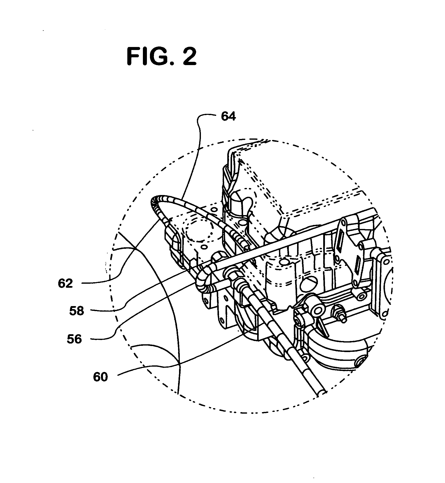
[0019] The valve actuator may be an air cylinder. Air pressure at an existing air manifold is modulated to the air cylinder by an air solenoid in accordance with the output of the ESC to properly position the deflector valve. A pulse width modulated motor may create a better blend-air effect than an air valve.

Problems solved by technology

Conditions like these may result in the charge air temperature being less than optimal for best engine operation during such conditions.
That in turn infringes on space that would be occupied by shutters.
That involves outlays not just for design services, but also for new tooling of various parts, and the costs incurred will have to be passed on, at least in part, to customers through price increases, an undesirable consequence in a competitive marketplace.

Method used


Image

  • System and method for controlling engine charge air temperature
  • System and method for controlling engine charge air temperature
  • System and method for controlling engine charge air temperature

Examples


Embodiment Construction

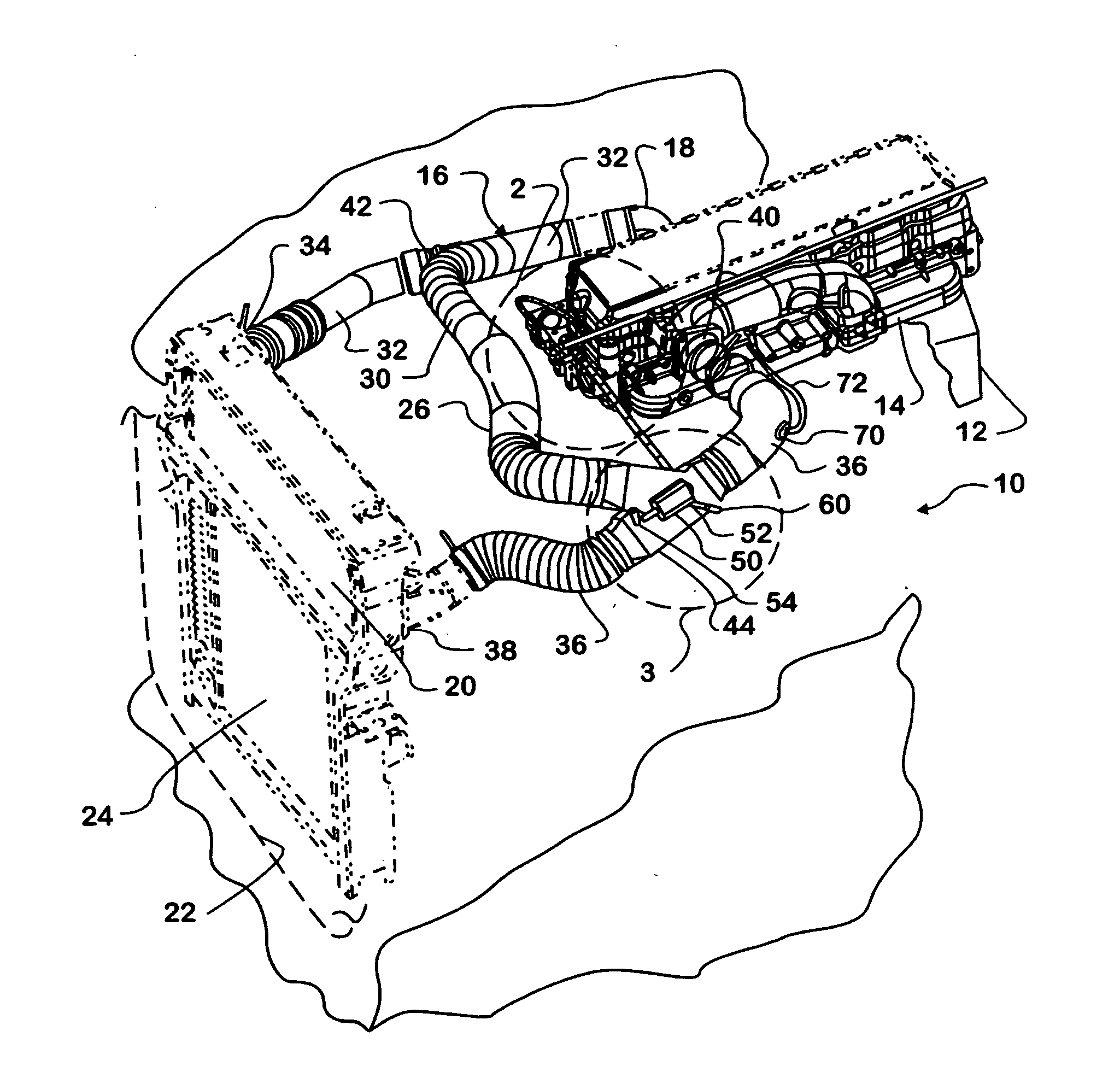
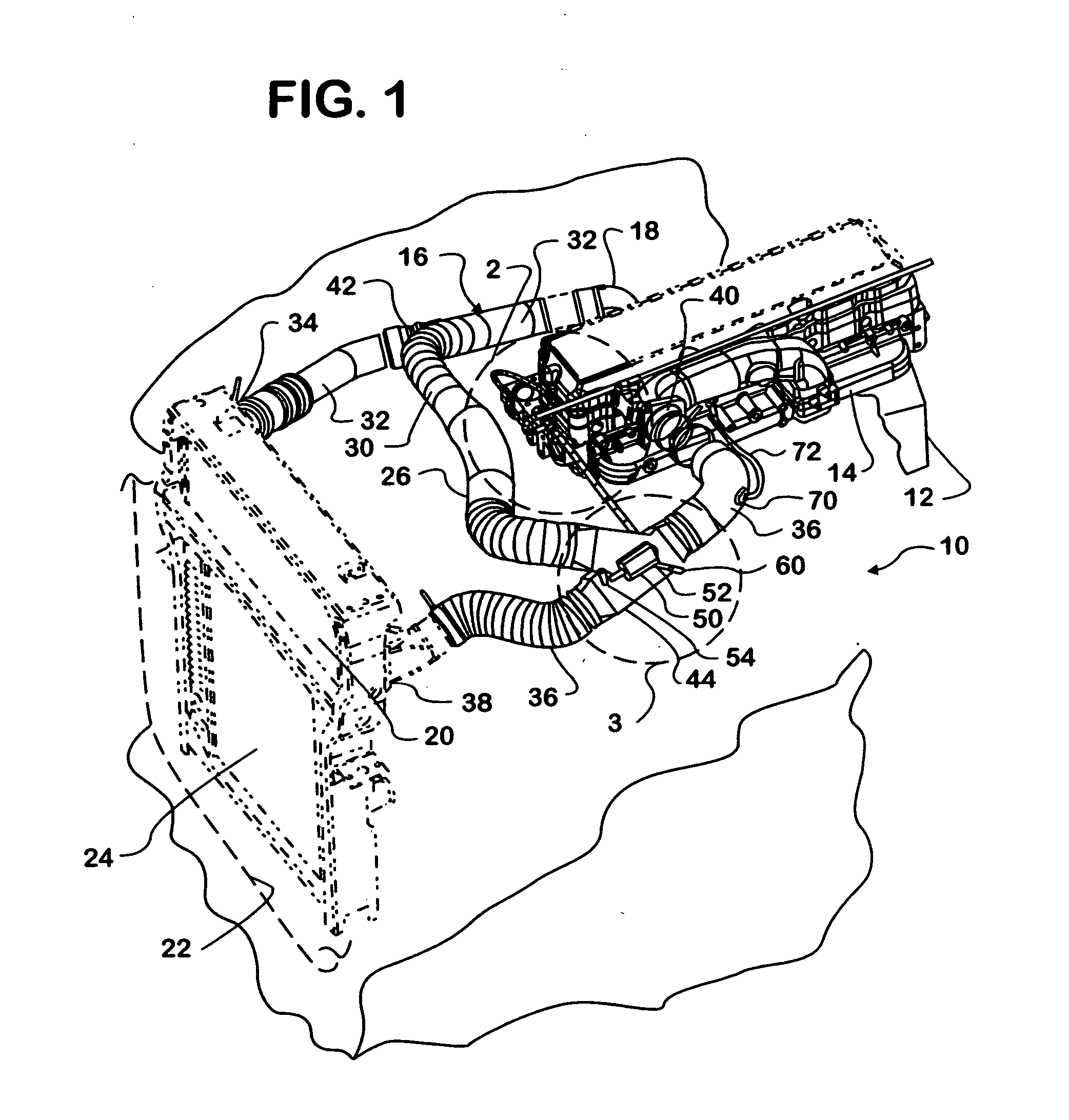
[0029]FIG. 1 shows contents of an engine compartment 10 of a heavy truck comprising a diesel engine 12 having an intake manifold 14 that is part of an air intake system 16. Additional components of air intake system 16 include a turbocharger 18 and a charge air cooler 20.

[0030] Turbocharger 18 is conventional and comprises a compressor operated by engine exhaust to draw ambient air into the intake system and create charge air that provides boost for engine 12. For removing at least some of the heat of compression from the charge air, the charge air can pass through charge air cooler 20 before it is delivered to intake manifold 14. Charge air cooler 20 is an air-to-air type heat exchanger, meaning one that utilizes air that passes through an air intake opening 22 into engine compartment 10 at the front of the truck to cool the charge air. A radiator 24 that cools engine coolant is also disposed in a portion of the engine compartment opening not occupied by charge air cooler 20. An a...


PUM


Abstract

A bypass (26) around a charge air cooler (20) and a control system (28) for apportioning the amounts of charge air passing through the bypass and the charge air cooler.

Description

FIELD OF THE INVENTION [0001] The present invention relates to internal combustion engines in motor vehicles, especially to an engine intake system that delivers charge air and a method for charge air temperature control in a diesel engine. BACKGROUND OF THE INVENTION [0002] The diesel engine industry is facing increasingly strict limits on certain undesirable constituents in diesel engine exhaust, such as oxides of nitrogen (NOx) and particulate matter (PM) emissions. After-treatment devices such as diesel particulate filters (DPF's) and NOx adsorbers are potential solutions for reducing PM and NOx emissions by physically trapping them. Alternative diesel combustion processes such as HCCI are also potential solutions because of their capability to limit formation of undesirable constituents. [0003] An important factor in the use of such potential solutions is the ability to control the temperature of the air that enters the engine cylinders for combustion. Diesel engines are today ...

Claims


Application Information

Patent Timeline
IPC IPC(8): F02B29/04F02D23/00F02B33/44
CPCF02B29/0456F02B29/0475Y02T10/146F02B33/44F02B29/0493Y02T10/12
Inventor BENDER, BURNELL L.
Owner INT TRUCK INTPROP LLC
Learn More